
 Send Email
-
Our Products
- Incinerator
- Electrical Incinerator With Scrubber
- Small Animal Incinerator
- Multi Purpose Shredder
- Mobile Waste Incinerator
- Industrial Waste Incinerator
- Garbage Shredder 5TPD
- Containerized Incinerator
- Napkin Incinerator With Scrubber
- Bio Medical Waste Incinerator
- Nano Sanitary Napkin Incinerator
- Electrical Incinerator With Venturi Scrubber
- Trommel Screening Machine
- Waste Baler
- Small Animal Waste Incinerator
- Glass Crushing Incineration Unit
- Rotary Kiln Incinerator
- Glass Crusher Incinerator
- Dry Waste Grinder
- Plastic Waste Shredder
- Food Waste Compost Machine
- Poultry Waste Incinerator
- Kitchen Waste Incinerator
- General Waste Incinerator
- Sanitary Napkin Incinerator
- Chicken Waste Incinerator
- Large Animal Waste Incinerator
- Rotary Kiln
- Napkin Incinerator With Smoke Control Unit
- Municipal Solid Waste Incinerator
- Human Body Cremation Furnace
- Bottle Crusher Incinerator
- E Waste Incinerator
- Large Poultry Waste Incinerator
- Domestic Waste Incinerator
- Marine Incinerator
- HIGH DENSITY BALERS
- TEKNIK QUAD BALER
- TRIPLE ACTION BALER
- CONTINUOUS BALER
- MINI TRIPLE ACTION BALER
- DOUBLE ACTION BALER
- SINGLE ACTION BALER
- HORIZONTAL BALING MACHINE
- Microtome Equipments
- Digital Tissue Processor 1 Liter
- Tissue Wax Block Storage Cabinet
- Slide Storage Cabinet Flat Position
- Mild Steel Cryostat Microtome
- Paraffin Dispenser
- Freezing Microtome
- Sliding Microtome
- Wood Microtome
- Sledge Microtome
- Cryostat Microtome
- Microtome Accessories
- Specimen Jar
- Slide Mounter
- Digital Microtome
- Rotary Microtome Erma Type
- Automatic Tissue Processor
- Rotary Senior Microtome
- Fully Automatic Microtome
- Paraffin Embedding Bath
- Slide Warming Table
- Microtome Object Holders
- Tissue Flotation Bath
- Automatic Teknik Vacuum Tissue Processor
- Automatic Razor Sharpener Spencer Type
- Tissue Processing Unit Automatic
- Tissue Culture Station Single Unit
- Slide Storage Cabinet
- Semi Automatic Microtome
- Microtome Razor
- Automatic Razor Sharpener Arthur Thomas Type
- Tissue Processor
- Teknik Automatic Tissue Processor
- Fully Automatic Tissue Processor
- Automatic Tissue Processor 1 Liter
- Automatic Teknik Tissue Processor
- Teknik Digital Tissue Processor
- Automatic Vacuum Tissue Processor
- Histology Vacuum Tissue Processor
- Vacuum Automatic Tissue Processor
- Automatic Tissue Processor Digital
- Tissue Processing Unit
- Automatic Tissue Processor Unit
- Teknik Tissue Processing Unit
- Vacuum Tissue Processor 1 Liter
- Fully Automatic Digital Tissue Processor
- Semi Automatic Microtome.
- CRYOSTAT MICROTOME
- ROTARY SENIOR MICROTOME
- Automatic Tissue Microtome
- Automated Stainer
- CRYOSTAT MICROTOME.
- Microscopy Equiptment
- Fluorescent Microscope
- Dissecting Microscope
- Inclined Microscopes
- Trinocular Microscopes
- Digital Microscope
- Metallurgical Microscope
- Dark Field Condenser
- Photomicrography .
- Polarimeter .
- Research Polarimeter
- Polarimeter Tubes
- Travelling Microscopes
- Abbe Refractometer
- Hand Refractometer
- Digital Refractometer
- Inverted Tissue Culture Microscope
- Binocular Pathological Research Microscope
- Electric Advance Projection Microscope
- Student Microscope
- Medical Microscopes
- Stereo Binocular Microscope
- Polarizing Microscopes
- Stereo Zoom Binocular Microscope
- Polarimeter Half Shade
- Trinocluar Metallurgical Microscope
- Medical Pathological Microscopes
- Co-Axial Concept Microscope
- Computer Compatible Microscope
- Operating Surgical Microscope
- Malaria Detection Microscopes
- Multi Viewing Microscope
- Inverted Tissue Research Culture Microscopes
- Optional Accessories for Microscopes
- Clean Air Systems
- FUME HOOD
- Garment Storage Cabinet
- Fume Hood
- Garment Storage
- Bio Safe Biological Safety Cabinet
- Air Curtains
- Vertical Laminar Air Flow Cabinets
- Sterile Material Storage Cabinet
- Horizontal Laminar Air Flow Cabinets
- Laminar Flow Cabinet Digital
- Inoculation Hood
- Teknik Dehumidifiers
- Tissue Culture Hood
- Sterile Garment Cabinet
- HORIZONTAL LAMINAR AIRFLOW
- Laminar Air Flow SS
- Air Showers
- Ceiling Laminar Airflow
- Portable Tissue Culture Rack
- Sampling And Dispensing Booth
- Ceiling Suspended Laminar Air Flow
- Uv Chamber With Uv Tube Light
- Biological Safety Cabinet Class II Type B2
- Biological Safety Cabinet Class III
- Biological Safety Cabinet Class I
- Static Pass Box
- DYNAMIC PASS BOX
- AIR SHOWER
- Heat And Refrigeration System
- Digital CO2 Incubator
- Seed Germinator Double Chamber
- Plant Growth Chamber
- RECTANGULAR (Stainless steel top)
- Kjeldahl Distillation and Digestion Unit
- DEHUMIDIFIERS .
- ENVIRONMENTAL SHAKER INCUBATOR
- Industrial Freeze Dryer
- Water Bath Incubator Shaker
- Laboratory Autoclave
- Freeze Dryer
- Vertical Autoclaves
- Universal Ovens
- COD Digester
- Seed Germinator Single Chamber
- Humidity Oven
- Vacuum Oven
- Bacteriological Incubator
- Tray Dryers
- Muffle Furnaces
- Hybridization Incubator
- Walk-in- Incubator
- Hot Plates
- Heating Mantles
- Distillation Stills Barnstead Type
- Serological Water Bath
- CELL PRODUCTION ROLLER APPARATUS
- Autoclave Rectangular
- Soxhlet And Digestion Units
- All Glass Distillation Apparatus
- Co2 Incubator Carbon Dioxide Incubator
- LYPHOLIZER TABLE TOP
- Co2 Incubator Shaker
- Co2 Incubator 6 Cubic Feet
- Stability Chamber Microprocessor Control
- Tabletop Freeze Dryer Lyophilizer
- Morgue Room
- STABILITY TEST CHAMBER
- Freeze Dryer Lyophilizer
- B O D Incubator
- Horizontal Autoclave
- CONTROLLED ENVIRONMENT CHAMBER
- Temperature and Precision Control Water Bath
- Laboratory Co2 Incubator
- Kjeldahl Distillation Unit
- Orbital Shaking Incubator
- Carbon Dioxide Incubator
- Refrigerated Water Bath
- Co2 Incubator
- Automatic Co2 Incubator
- Teknik Laboratory Co2 Incubator
- Co2 Incubator Laboratory Equipment
- High Temperature Oil Bath
- Teknik Automatic Co2 Incubator
- Seed Dryer Cabinet
- Rectangular Water Bath
- Lyophilizer Freeze Dryer
- Distillation Stills Manasty Type Wall Hanging
- Vertical Freeze Dryer
- Teknik Freeze Dryer
- Lab Freeze Dryer
- Food Freeze Dryer
- Vacuum Freeze Dryer
- Laboratory Lyophilizer Freeze Dryer
- Benchtop Lyophilizer Freeze Dryer
- Teknik Lyophilizer Equipment
- Laboratory Lyophilizer Freeze Dryer 3kg
- Lyophilizer Freeze Dryer 10kg
- Industrial Lyophilizer Freeze Dryer
- Teknik Lyophilizer Freeze Dryer
- Freeze Dryer Vertical Type
- Horizontal Freeze Dryer
- Freeze Dryer 200 L H
- Freeze Dryer Lab Scale
- Laboratory Scale Freeze Dryers
- Freeze Dryer -80C
- Laboratory Freeze Dryer Machine
- Lab Lyophilizer Freeze Dryer
- Freeze Dryer 43 Liters
- Freeze Dryer -40C
- Touch Screen Tissue Flotation Water Bath
- Tissue Flotation Bath.
- MAGNETIC STIRRER WITH HOT PLATE .
- MAGNETIC STIRRER WITHOUT HOT PLATE .
- ELECTRONIC WEIGHING BALANCE
- HOT AIR OVEN
- OVEN INCUBATOR ( VACUUM DRYING OVEN)
- INCUBATOR .
- BOD INCUBATOR
- STABILITY CHAMBER
- CONTROLLED ENVIRONMENT CHAMBER .
- Refrigerated Equipments
- Blood Bank Instruments
- Cooling Compartment
- Blood Bank Freezer
- Blood Bank Monitor
- Syringe Needle Destroyer
- Blood Bank Scale
- Plasma Extractor
- Donor Couch
- Blood Tube Roller Mixer
- Plasma Thawing Bath
- Cryo Bath
- Burner, Bunsen
- Medical Refrigerator
- Blood Bank Refrigerator
- Blood Grouping Tiles
- Blood Bag Sealer
- Blood collection monitor
- Centrifuge, Haematocrit, Electric, With Reader
- Biosafety Cabinet, Class 1
- Platelet Agitator With Incubator
- Pharmacy College Equipments
- Four Unit Organ Bath
- Student Induction Coil
- Hand Grip Dynamometer
- Compass Aesthesiometer Pharmacy College
- Embalming Table
- Standard X Block
- Hook and Weight
- Small Animal Holder
- Induction Coil
- Spirometer .
- Simple Key
- 12w Student Nerve Muscle Assembly
- Muscle Grip
- Starling Crank Myograph
- Power Table
- Open Sided X Block
- Dubois Raymond Key
- Heart Clips
- New Nerve Muscle Chamber Lucas Moist Chamber
- Variable Interrupter
- Rat Operating Table
- Organ Jar Bath Digital
- Simple Electrode
- Varnishing Tray
- Pneumograph Stethograph
- Animal Head Holders
- Lagendroff Assembly
- Skin Fold Caliper
- Operating Table
- Student Electrical Kymographs
- Student Isometric Lever
- Small Animal Operating Table
- Long Paper Extension
- Manometers .
- Time Recording Devices
- Frog Board
- Digital Respinometer
- Simple Lever
- Mosses Ergograph
- Macerator .
- Isolated Organ Baths Digital
- FIRST AID KIT
- General Lab Equipments
- Dissection Kit .
- Vacuum Centrifuge .
- Magnetic Stirrer Heavy Duty
- Lamp With Socket E10
- Metal Blades With Iron Marking
- Safety Glasses .
- Metal Blades With Lead Marking
- Floating Material in Dry Powder
- Resistors 3 W
- Spoon Weighing .
- Compact Laboratory Centrifuge
- Color Synthesizer .
- Clinical Centrifuge Machines
- Precision Digital Melting Point Apparatus
- Blood Group Determination Kit
- Autopsy saw with dust collector
- PRESSSIOMETER . .
- Piston Pipeers .
- Arterial Pressure .
- Thermal Conduction Bars
- Hygrometer . .
- Laplace Rail .
- Aneroid Barometer .
- Kit Synthese of Nylon
- Speakers Highlighting Breathing
- Plateau Weights Person
- Air Cushion Table
- Pendulum Weighing Device
- Membrane Melde Vibrator
- Horizontal Perroquet Scale
- Pair of 440 Hz Diapasons on Board of Resonance
- Iron Lime Plastic Box
- 12v / 24w Mirror Light Source
- Spectral Tubesdesignation
- Freez Cube Freezer
- Graduated Metal Lever
- BAROMETER . .
- Objects Diffraction: Set of 5 Slides
- Electronic Assembly .
- Multimeter- Thermometer - Dc Voltmeter
- SUPPORT COIL .
- Circular Demonstration Dynamometers
- Metal Clamp for Test Tube
- Tightening Nuts .
- Cylinders of Equal Volumes
- Vortex Mixer .
- Shoe Cover Dispenser
- Apparatus Study of Molecular Movements
- Milliampere meter. .
- Edge Scales .
- Ph Paper .
- Cutter Clamp .
- Pivot Nut Clips
- Angular Sensor .
- Dynamometer . .
- Cage of Faraday .
- Coulomb / Newton Forces Device
- Black 3W Resistors
- Potentiometer Potentiometer .
- FILTRATION CODENSATOR 4700 F
- Moufle Prehending .
- Protected Speaker .
- Magnetic Needle .
- Demonstration Alternator .
- Optical Bench .
- Boxes With Decades of Capacity
- Cordon Bnc .
- TRANSFORMER 6 V / 24 V
- Electric 3W Resistors
- Model Eye .
- Amperemeter . .
- Masses Marked .
- Thin Layer Chromatography Apparatus
- Spectrogoniometers . .
- Pocket Ph- Meter .
- Shaking Machines Rotary
- Boxes With Resistance Decades
- Disc With Index .
- Calibrated Springs With Index
- Isostatic Model .
- Double Spatula With Spoon
- Vacuum Bell With Integrated Pump
- Boxes With Decade of Inductors
- Immersion Probes for Manometric Tube
- Power Supply for Spectal Tubes
- Pliers . .
- Right Magnet
- Sample Dispensing Booth
- Metallic Table
- Lab Magnets
- Luminous Frame and Dissection Tank
- Aluminum Blade .
- Universal Imager Ease
- Resistivity Analysis Application
- Wooden Clips .
- Fixing Brackets
- Graaff Van Generator
- Analogue Oscilloscopes Bicourbe
- Magnetic Stirrers .
- Lab Stirrer
- MELTING POINT APPARATUS
- CENTER GRID CERAMIC
- Transmitter-usb Receiver .
- 2-way Digital Oscilloscopes
- Battery Studing Device
- Pipettes Pasteur in Polypropylene
- Function Generators 2 Mhz
- Water Manoscope Set 660g Env
- Rotary Vacuum Pumps
- Filament Bulbs E10
- Pivoting Hook Dynamometers Graduations
- Serum Inspissator .
- WATER BATH .
- Shielded Light Emitting Diode
- Oxymeter O2 Water
- Electro - magnet .
- Manual Pump Vacuum Speaker
- Metallic Cylinders of Equal Mass (56 G)
- Caps . .
- Magnetic Rule Graded on Magnet
- Spheres With Ring
- Micophone Hq .
- Shaking Machine Sieves Rotor Type
- Metal Blades Without Copper Marking
- Cutter-tube With Wheel
- Frequency Meter .
- Dipole Holder with Flap Connectors
- Metallic Starstar With 5 Metal Branches
- Cordon Bnc for General lab
- Metal Blades With Zinc Marking
- Single Knife Switch for labs
- Racks for Test Tubes
- Switch . .
- Replacement Tank Basin
- Digital Magnetic Stirrer With Hot Plate
- Electronic Kundt Tube
- Electrocardiogram . .
- Shaking Machine Kahn Rack Type
- Thermometer . .
- Hand Centrifuge .
- 3W LED Binocular Microscope
- PINS . .
- Filament Bulbs for labs
- Atomic Model .
- Rubber Sealing Conves
- Vortex Mechanical Agitator
- SOLAR CELL .
- Refrigerated Centrifuge .
- Doppler Effect and Speed Monitor Bench
- Parafilm . .
- Millivoltmeter Ac/Dc .
- Thermometer and Thermocouple .
- Ultrasound Telemeter .
- Alcoold Pyrometer .
- U - core .
- Vincilab Interface .
- Wimshurst Machine .
- TESLAMETER . .
- Cotton Lab Coat .
- Balance De Roberval
- RIVER DEBIMETER .
- Student Sleep Chamber
- Co2 Meter .
- Voltmeter Ac/Dc .
- Accelerometer . .
- VDRL Rotators And Shaker
- Hole . .
- Us Receiver Housing
- Filtration Codensator 4700
- Fully Transparent Calorimeter
- Projectable Magnetic Circuits
- Shaking Machine Table Model
- Helmotz Coil .
- Plumb -line .
- Single Banana Cords Reverse Release
- Digital Automatic Melting Point Apparatus
- Multifunction Laser .
- Wind Energy Conversion Apparatus
- Demonstration Spring .
- Variable Induction Coil 1.7 H
- Laser Optics Box 5 Beams
- Digital Thermometers .
- Perce Caps Apparatus .
- Luminous Intensity .
- Detachable Transformer .
- 3d Giant Magnetic Spectators
- Accessories for Ultrasonic Study
- Thermotubes the Marie Bath Without Water and Without Risk
- Tissue Homogenizers .
- Inclined Plan .
- Led Demonstration Wavewich
- Radioactivity . .
- Masses Box 210g
- BOSSOLE 3D .
- Single Pendulum With Variable Parameters
- Single Banana Cords Reverse Rear Length
- Heating Magnetic Stirrer
- Shaking Machine Wrist Action
- Spirometer . .
- PROTECTED LED .
- Optical Fork and Pulley
- Spectral Tubesdesignation: Hydrogen
- Any Form on Magnet
- Aluminium Filament Bulbs E10
- Slide Dryer .
- COULOMBMETER . .
- Ph Connection Electrode
- Binocular Stereo .
- Pulley on Magnet
- Plug-in Transformer .
- Atomic Boxes .
- Thermo generator
- Melting Point Apparatus
- Fixed Power Supplies
- Xenon Lamp Strobe
- Deionizers Equipment
- Electrostatic Pendulum .
- Free Fall With Digital Displays
- Oxymeter O2 Air
- Ph Tester Pen
- Laser Information Transmission Assembly
- Sonometer . .
- FUSE ON SUPPORT
- Magnetic Support .
- DC Electric Motor Model Kit
- Kit Complement Transformer
- Dispensing And Sampling Booth
- Tissue Slide Dryer
- Combination Tissue Flotation Bath and Slide Dryer
- Pathology Equipment Tissue Slide Oven Slide Dryer Slide Warmer
- Paraffin Wax Dispenser
- Closed Automatic Tissue Dehydrator
- Fully Automated Coverslipping Workstation
- MAGNETIC STIRRER WITH HOT PLATE
- MAGNETIC STIRRER WITHOUT HOT PLATE
- ELECTRONIC WEIGHING BALANCE
- WATER DISTILLATION UNIT
- AUTOMATIC PH METER .
- VACUUM PUMP
- MELTING POINT APPARATUS .
- WATER BATH . .
- Pharmaceutical Lab Equipment
- Microprocesser Disintegration Test Apparatus
- Antibiotic Zone Reader
- Bottle Cap Sealing Machine
- Bottle Washing Machine
- Bottle and Liquid Filling Machine
- Collapsible Tube Ointment Filling Machine
- Capsule Filling Machine
- Small Animal Cage
- Dissolution Rate Test Equipment
- Membrane Filter Holder
- Propeller Type Mechanical Agitator
- Rotary Vacuum Flash Evaporator .
- Tablet Making Machine Electrically Operated
- Tablet Making Machine Motorised
- Tube Crimping Machine
- Tablet Hardness Tester .
- Tablet Hardness Tester
- Radiant Heat Digital Type
- Flash Point And Fire Point Apparatus
- Ir Moisture Balance
- Microprocesser Fribility Test Apparatus
- Mild Steel Ball Mill
- Eddys Hot Plate
- COUNTING TRAY, TABLET
- Ampoule Filling And Sealing Device
- Cannulae .
- Anderson Pipette
- Conical Percolator
- Cone Blender
- Cage Metabolic
- Disintegrator .
- Bulk Density Apparatus
- Filtration Assembly
- Filtration Unit
- Granulating Sieves
- Lipstick Molds
- Ointment Slab
- Plythesmography .
- Rabbit Holder
- Digital Rheometer
- Suppository Mould
- Sietz Filter
- Tablet Counter
- Tincture Press
- Hammer Grinder
- Telethermometer .
- Actophotometer .
- Analgesiometer .
- Electro Convulsometer
- Rota Rod
- Metronome .
- Stimulator .
- Electrophoresis Apparatus
- Power Supply
- Digital Viscometer
- Perimeter .
- Tablet Friability Tester
- Encapsulated LED
- Membrane Filter Holder- All glass
- Blender .
- V Cone Blender
- Pole Climbing Apparatus
- Ampoule Washing Device
- Disintegration Test Machine
- Friability Test Apparatus
- Hand Grind Mill
- Jar Test Apparatus
- Laboratory Wiley Mill
- Sterility Test Apparatus
- Tablet Making Machine
- Tablet Coating Pan
- Tablet Polishing Pan
- Sigma Blade Mixer
- Paper Electrophoresis Apparatus
- Disintegration Test Machine for Lab Use
- Microprocessor Based Dissolution Test Apparatus
- Vertical Slab Gel Electrophoresis Apparatus
- Sonicator Bath And Ultra Sonic Cleaner
- Mixing Vat With Stirrer
- Dissolution Rate Test Equipment with rpm setting
- Dissolution Rate Test Equipment for Pharmaceutical Lab
- Histamine Chamber
- Colloidal Mill
- Medical Anatomy Instruments
- 6 Body Mortuary Chamber
- Two Body Cool Mortuary
- Dead Body Freezer
- Autopsy Table .
- Embalming Machine .
- Refrigerator, Mortuary .
- Suction Apparatus .
- Six Body Mortuary Chamber
- Funeral Chamber .
- Cold Room .
- Three Body Cool Mortuary Chamber
- Vacuum Extractor .
- Meat Cutting Machine
- Four Body Mortuary Chamber
- Touchscreen Pathology Workbench
- Single Body Mortuary Chamber
- 2 Rooms Side Open Mortuary Refrigerator
- Mortuary Corpses Storage Rack .
- STEAM STERILIZER .
- CHURCH COLLAPSABLE COFFIN TROLLEY
- Rotatable And Liftable Autopsy Table
- TRIMMING STATION-DOWN DRAFT
- Manual Hydraulic Mortuary Lift
- Mortuary Cold Storage System
- Mortuary Corpse Trolley with Liftable Side
- Mortuary Chamber For 9 Bodies
- Bone and Meat Cutting Machine
- Cadaverous Injector .
- SS Mortuary Freezer
- 8 Body Mortuary Chamber
- Mortuary Cold Rooms
- Cold Room for mortuary
- Mortuary Cold Room Unit
- 9 Body Mortuary Chamber
- Teknik Mortuary Equipment
- Teknik Mortuary Chamber
- Teknik Mortuary Cabinet
- Dead Body Freezer Box Mortuary
- Mobile Mortuary Freezer
- Mobile Dead Body Mortuary Freezer
- Cold Storage Facility For Mortuary
- Mobile Mortuary Trolley
- 2 Capacity Bodies Mortuary Chamber
- 2 Body Mortuary Chamber
- Mortuary Chamber 4 Body
- 3 Body Mortuary Chamber
- Mortuary Chamber 3 Body
- 3 Body Mortuary Cabinet
- Three Body mortuary chamber
- 12 Body Mortuary Chamber
- Two Body Mortuary Chamber
- Teknik Cadaver Trolley
- Stainless Steel Autopsy Table
- Mortuary Embalming Table
- 4 Body Mortuary Chamber
- Anatomy Cadaver Tank
- MORTUARY TROLLEY FOR SHIFTING DEAD BODIES
- TEKNIK DEAD BODY/MORTUARY CHAMBER FIBER TOP
- 3 Rooms Mortuary Refrigerator
- Electrial Mortuary Lift
- Stainless Steel Body Tray
- Adjustable Body Preservation Tank
- Cadaver Body Tank Immersion Dissection Table
- Mortuary Corpses Storage Rack
- Mortuary Trolley .
- Morgue Trolley with Side Opening Cover
- Formalin Dispenser .
- 3 Rooms Side Open Mortuary Refrigerator
- Church Coffin Trolley
- Mortuary Dead Body Transfer Trolley
- Mortuary Dead Body Transport Trolley With Cover
- Mortuary Corpse Trolley with Fixed Tray
- Mortuary Corpse Cart with Removable Tray
- Electric Two Scissors Mortuary Body Lift
- Two Scissors Manual Mortuary Lift
- One Corpse Mortuary Refrigerator With Foldable Trolley
- 4 Rooms Mortuary Refrigerator
- 9 Floors Mortuary Refrigerator
- 6 Rooms Mortuary Refrigerator
- 8 Bodies Mortuary Refrigerator
- 2 Bodies Rooms Morgue Refrigerator
- Funeral Casket Lowering Device
- Grossing Table
- TWO ROOMS SIDE OPEN MORTUARY REFRIGERATOR
- THREE ROOMS SIDE OPEN MORTUARY REFRIGERATOR
- TEN BODY MORTUARY CHAMBER
- TWELVE BODY MORTUARY CHAMBER
- FIFTEEN BODY MORTUARY CHAMBER
- AUTOPSY TABLE
- LIFTABLE DISSECTION TABLE
- DISSECTION TABLE .
- MORTUARY DEAD BODY FULLY LIFTABLE TRANSFER TROLLEY
- MORTUARY DEAD BODY TRANSPORT TROLLEY WITH REMOVABLE COVER
- MORTUARY TROLLEY WITH ELECTRIC LIFTING
- EYE WASHER .
- INSTRUMENT TROLLEY .
- AUTOPSY SAW .
- PLASTER CUTTER SAW
- PLASTER CUTTER SAW WITH DUST COLLECTOR
- DISSECTION TABLE.
- DISSECTION TABLE AND CADAVEROUS STORAGE TANK
- GROSSING STATION
- DISSECTION SINK
- DISSECTION WORK STATION WITH SINK
- TWO BODY ROTATING DISSECTION TABLE
- STANDARD ANATOMY DISSECTION TABLE
- DISSECTION TABLE WITH RIGHT SINK
- HYDRAULICS AUTOPSY TABLE
- BODY WASHING UNIT
- CABIN FOR WASHING ORGANS
- Laboratory Glassware
- 2000ml Bottom Shapes Pyrex With Spout
- Volumetric Flask With Stopper Leak Proof
- Transparent Gauge Pipettes With Safety Ball
- Adapter Socket To Rubber Tubing
- Graduated Glass Cylinders
- Graduated Pipettes .
- Glass Funnels .
- Borosil Erlnmeyers Narrow Neck
- Cone Plain Double
- WATCH Glass .
- Erlenmeyer Flasks, Narrow Neck with graduation
- Graduated Pipettes for Laboratory use
- Storage Bombonne .
- Separating Funnels With Ptfe Key
- GRADUATED PIPETTES .
- Steam Distillation Heads and Sloping
- Flask Round Bottom Single Neck DIN12348 Medium
- Transparent Bottom Shapes Pyrex With Spout
- Flasks Pear Shape single neck
- Multiple Adapters With Two Necks Parallel
- Sockets Double .
- Reactional Assemblies Rody Glass
- Graduated Pipettes .
- Flasks Iodine with stopper
- Transparent Graduated Glass Cylinders for Laboratory
- Recovery Bend and Sloping
- Transparent Volumetric Flask With Stopper
- Flask Round Bottom narrow neck, with beaded rim
- Two-Neck Multifunctional Adapter
- Cones With Tip Single
- Claisen Heads and Sloping With 2 X B14 Socket
- Flasks Round Bottom, Three Neck at Parallel/angle
- Sockets Full Length Single
- Drying Tube .
- Flasks, Buckner Filtration Bolt Neck
- Multiple Adapters With Three Necks
- Manual Volumetric Flask With Stopper
- Standard size Bottom Shapes Pyrex With Spout
- 100ml transparent Bottom Shapes Pyrex With Spout
- Flasks, Distillation with side Tube
- Flask Flat Bottom and Narrow Neck
- Graduated Glass Cylinders for Laboratory Glassware
- Volumetric Flask With Stopper Glass material
- Borosilicate Volumetric Flask With Stopper
- 1ml capacity Gauge Pipettes With Safety Ball
- Manual Gauge Pipettes With Safety Ball
- Gauge Pipettes With Safety Ball for Laboratory
- Squeeze Bottles with Cap and Colored Nozzle
- Dispensing Bottles with Colored Spout and Cap
- Receiver Adapters Bend With Vent
- Crystallisers With Thickener
- Crystallisoirs With Thickener
- Mohr Burt With Ptfe Faucet Class
- Tests Chemical Resistance Graduated Glass Cylinders
- Polypropylene Support for Bulb
- Bulbs to Be Decorated Glass Faucet
- Transparent Graduated Glass Cylinders
- Erlnmeyers Narrow Neck for Laboratory Glassware use
- Transparent Erlnmeyers Narrow Neck
- MORTAR AND PESTLE
- Stopper Polypropylene .
- Cone Full Length Plain End Single
- Sockets Single .
- Stopper Hollow With Flat Bottom
- Splash Heads and Pear Shape Vertical
- Flasks, Evaporating (Buchi Flask)
- Adapters Cone To Rubber Tubing Right Angle Connection
- Cones Single .
- Boro 3.3 Glass Test Tubes
- 100ml Volumetric Flask With Stopper
- Flask Round Bottom wide neck
- Pycnometer With Cape
- Receiver Adapters With Multiple Connection
- Flask Flat Bottom and Wide Neck
- 1000ml Bottom Shapes Pyrex With Spout
- U Tube With Two Sockets With Stopper
- Stopper Solid Penny Or Flat Head
- Rodaviss Reaction Assemblies
- 10ml Gauge Pipettes With Safety Ball
- GAUGE PIPETTES WITH SAFETY BALL
- Volumetric Flask With Stopper
- Graduated Pipettes for Laboratory Glassware
- Bottom Shapes Pyrex With Spout
- Graduated Glass Cylinders for Laboratory
- Plastic Joint Clips colour coded
- Dropper Bottles .
- Eco Dessicator .
- 1000ml Graduated Glass Cylinders
- Erlnmeyers Narrow Neck
- Reduction Adapters .
- Expansion Adapters .
- Adapters Cone With Stem To Rubber Tubing
- Splash Heads and Adapter Vertical
- Dual-Neck Multiport Adapter
- Receiver Delivery Adapters Long Stem
- Receiver Delivery Adapters Short Stem
- Receiver Bend and Vertical
- Receiver Adapters Straight With Vacuum Connection
- Receiver Adapters and Bend With Vacuum Connection
- Flasks, Conical, with Ptfe Liner Screw Cap
- Receiver Adapters Plain Bend and Receiver Bend
- Receiver Adapters Perkin
- Still Head Plain With Thermometer Socket
- Air Leak Tube Gas Inlet Tube
- Flasks Round Bottom, Two Neck DIN12394 parallel/angle
- Splash Heads and Pear Shape Sloping
- Thermometer Pocket .
- Adapter Cone To Rubber Tubing
- Adapters Sockets To Rubber Tubing, Straight Connection.
- Adapters Socket To Cone With Tee Connection.
- Joint Clips Metal
- Simple Glands with cap (Thermometer Adapter)
- Retort Stoppered .
- Flasks Pear Shape Two Neck
- Flasks, Conical (Erlenmeyer) DIN 12387 Jointed
- Flasks Kjeldahl Jointed
- Volumetric Flask .
- Erlenmeyer Flasks Wide Neck
- Receiver Adapters Straight
- Swan Neck Adapters
- Psychology Equipments
- Analytical Lab Instrument
- Ammonium Ion Specific Electrodes for Analytical Labs
- Field Digital Ph Meter
- Micro Controller Ph Meter
- Field Turbidity Meter
- Field Conductivity Meter
- Digital Colony Counter
- Digital Auto Karl Fischer Titiri Meter
- Microprocessor Karl Fischer Titrimeter
- Atomic Absorption Spectrophotometer
- Digital Hemoglobin Meter
- Water and Soil Analysis Kit
- Bio Chemistry Analyzer
- Digital Analytical Viscometer
- Digital Automatic Melting Point Apparatus .
- Digital Photo Fluorometer
- Digital Automatic Polarimeter
- Tissue Embedding Center with Cold Plate
- Ammonium Ion Specific Electrodes for General Labs
- Deluxe Ph Meter
- LAB Conductometer
- Digital Auto Colorimeter Analyzer
- Digital Nephelometer
- Digital Potentiometer
- Digital Spectrophotometer
- Ftir Spectrometer
- Digital Blood Cell Counter
- Digital Tele Thermometer
- Digital UV-Visible Spectrophotometer
- Microprocessor Conductivity And Tds Meter
- Hemogram Meter
- Microplate Reader
- Colorimeter Range : 430 - 470 - 565 - 635 Nm
- Ph- Meter
- Digital Flame Photometer .
- Digital Conductivity Meter
- Colorimeter, With Concentration Reading
- Counting Chamber Set, Fuchs-rosenthal Ruling And Neuberger Ruling
- DIGITAL CONDUCTIVITY METER
- Electrode Ph
- Counter, Differential, Cell
- Electrodes Specific to Chloride Ions
- Gas Chromatograph Mass Spectrometer
- Semi Automatic Water and Soil Analysis Kit
- Specific Calcium Ion Electrodes
- Digital Salinity Meter
- Digital Auto Calorimeter
- Microprocessor Photo Calorimeter
- Digital Turbidity Meters
- Microprocessor Conductivity Meter
- Digital Tds Meter
- Field Tds Meter
- Microprocessor Turbidity Meter
- Digital Flame Photometer
- Microprocessor Hemoglobin Meter
- Portable Hemoglobin Meter
- Microprocessor Flame Photometer
- Digital PH Conductivity
- Microprocessor Ph / Temp / Mv Meter
- Digital Ph Meters
- Microprocessor Ph Meter
- Precision Digital Melting Point Apparatus .
- Microprocessor Based Conductivity And Tds Meter
- Microcontroller-Based UV-Vis Spectrometer
- Water and Soil Analysis Kit for Analytical Lab
- Tissue Embedding Center & Cooling Plate
- DIGITAL PH METER
- TDS METER
- Pharmacology Equipments
- Boss Heads Stands And Fixing Devices
- Surgical Paper Extension
- Long Paper Smoker And Varnisher
- Frog Heart Chamber
- Student Kymographs Digital
- unbreakable Single Knife Switch
- Brodie Starling Kymograph
- Bicycle Ergograph
- Student Physiograph
- Polygraph .
- Digital Polygraph
- Animal Holders
- Research Kymograph
- Hook And Weight
- Gimbal Lever
- Fixit Lever
- Myographic Lever
- Tambours .
- Muscle Twitch Assembly
- Smoking And Varnishing Outfits
- Brodie Universal Lever
- Heart Lever Starling
- Frog Muscle Chamber
- Brodie Operating Table
- Benedict Roth Recording Spirometer
- Student Nerve Muscle Assembly for Pharmacology use
- Medical furniture
- Hospital Bed
- Hospital Bed Side Screen
- Electric Motorized Hospital Bed
- Semi Fowler Bed
- Examination Couch
- Hospital Plain Bed
- Hospital Cot
- Pediatric Bed
- Drug Cabinet
- Instrument Cabinet
- Trolley Instruments
- Trolley .
- Bed Cradle
- Bed, Hospital Adult, Basic
- Delivery Bed
- Bed, Hospital Adult
- Fowler Hospital Bed
- Electric ICU Bed
- Hospital Gyne Delivery Bed
- Gynec Examination Couch
- Adjustable Hospital Bed
- Hospital Attendant Bed
- Wire Mess Hospital Bed
- Manual ICU Bed
- Hydraulic Delivery Bed
- Waterproof Dead Body Corpse Bag With Handles
- Mass Transfer Lab Equipments
- Liquid-Liquid Extraction In Packed Tower
- Packed Distillation Column
- Absorption In Packed Bed
- Natural Draft Tray Dryer
- Forced Draft Tray Dryer
- Fluidised Bed Dryer
- Vapour Liquid Equilibrium Setup
- Solids Handling Study Bench
- Change of State of Gases
- Ion Exchange Unit
- Laboratory Steam Generator
- Solid And Liquid Extraction Unit
- York Scheibels Extraction Unit
- Bubble Cap Distillation Column
- Sieve Plate Distillation Column
- Freeze Drying Machine
- Solid Liquid Extraction Unit
- Spray Tower
- Absorption In Sieve Plate Column
- Absorption In Wetted Wall Column
- Vapour In Air Diffusion Apparatus
- Solid In Air Diffusion Apparatus
- Rotary Dryer
- Batch Crystallizer
- Tulip Electricalizers
- Steam Distillation Setup
- Adsorption .
- Ph Control
- Trainer for Various Heat Exchangers
- Uv Visible Spectrophotometer for Mass Transfer Lab Equipments
- Viscometer Viscometer
- Absorption Chiller
- Thermo Gravimetric Analyzer (Tga)
- Bet Surface Area and Pore Size Analyzer and High Pressure Analyzer
- Fuel Cell System
- Multi Position Stirrers
- table mounted Uv Visible Spectrophotometer
- Coulometric Karl Fischer Titration System With Titration Controller and Titration Module
- Swenson Walker Crystallizer
- LIQUID- LIQUID EXTRACTION IN A PACKED TOWER APPARATUS
- YORK SCHEIBEL EXTRACTION UNIT APPARATUS
- SPRAY TOWER APPARATUS
- BUBBLE CAP DISTILLATION COLUMN APPARATUS
- SIEVE PLATE DISTILLATION COLUMN APPARATUS
- STEAM DISTILLATION COLUMN APPARATUS
- ABSORPTION IN SIEVE PLATE COLUMN APPARATUS
- ABSORPTION IN PACKED BED APPARATUS
- ABSORPTION IN WETTED WALL COLUMN APPARATUS
- VAPOUR IN AIR DIFFUSION APPARATUS
- SOLID IN AIR DIFFUSION APPARATUS
- NATURAL DRAFT TRAY DRYER APPARATUS
- FORCED DRAFT TRAY DRYER APPARATUS
- ROTARY DRYER APPARATUS
- FLUIDIZED BED DRYER APPARATUS
- BATCH CRYSTALLIZER APPARATUS
- SWENSON WALKER CRYSTALLIZER APPARATUS
- VAPOUR-LIQUID EQUILIBRIUM SET-UP APPARATUS
- MASS TRANSFER WITH & WITHOUT CHEMICAL REACTION (SOLID -LIQUID) APPARATUS
- EXPERIMENTAL WATER COOLING TOWER APPARATUS
- ION EXCHANGER APPARATUS
- HUMIDIFICATION & DEHUMIDIFICATION SETUP APPARATUS
- SOLID-SOLID EXTRACTION APPARATUS
- SIMPLE BATCH DISTILLATION SETUP APPARATUS
- VACUUM TRAY DRYER APPARATUS
- Chemical Engineering Laboratory Equipments
- Double Water Distiller
- EMULSION POLYMERIZATION SET-UP APPARATUS
- ISOTHERMAL CONTINUOUS STIRRED TANK REACTOR (C.S.T.R.) APPARATUS
- Chemical Reactor Training Equipment
- Laboratory Pasteuriser
- Aerobic Digester
- Anarobic Digester
- Rapid Extractor
- HAND OPERATED CASAGRANDE EQUIPMENT
- Quartz Water Distillation Equipment
- Single Stage Quartz Water Distillation
- All Quartz Water Distillation Cabinet
- Quartz Water Distillation Apparatus
- Fluidisation And Fluid Bed Heat Transfer Unit
- Chiller Water Bath
- Field CBR Equipment
- Sedimentation Studies Apparatus
- Liquid Chromatograph Digital
- Gas Absorption Column
- Rising Film Evaporator
- ABSORPTION IN PACKED COLUMN
- All Quartz Water Distillation Equipment Cabinet
- KINETIC OF DISSOLUTION OF BENZOIC ACID APPARATUS
- SPIN INNING BASKET REACTOR APPARATUS
- Reverse Osmasis Ultra Filteration Unit
- Thermal Conductivity of Metal Rod for Chemical Engineering Laboratory
- Flow Through Helical coil
- Batch Enzyme Reactor
- COMBINED FLOW REACTOR APPARATUS
- Water Distillation Equipment
- Teknik Distilled Water Lab Equipment
- Quartz Subboiling High Pure Water Distiller
- Automatic Water Distillation Equipment
- Automatic Water Distillation Equipment Cabinet
- Water Distillation Equipment Cabinet
- Distilled Water Equipment Cabinet
- Teknik Quartz Water Distillation Equipment
- Water Distillation Unit Quartz Teknik
- Water Distillation Unit Quartz
- Quartz Water Distillation Equipment Cabinet
- CONTINUOUS STIRRED TANK REACTOR (C.S.T.R.) APPARATUS
- ISOTHERMAL BATCH REACTOR APPARATUS
- ISOTHERMAL SEMI-BATCH REACTOR APPARATUS
- PACKED BED REACTOR APPARATUS
- R.T.D. STUDIES IN PACKED BED REACTOR APPARATUS
- CHEMICAL REACTOR SERVICE UNIT APPARATUS
- ADIABATIC BATCH REACTOR APPARATUS
- LIQUID PHASE CHEMICAL REACTOR APPARATUS
- HYDRODYNAMICS OF TRICKLE BED REACTOR APPARATUS
- UV-PHOTO REACTOR APPARATUS
- RECYCLE BED REACTOR APPARATUS
- CONDENSATION POLYMERIZATION SET-UP APPARATUS
- CASCADE CONTINUOUS STIRRED TANK REACTOR (CASCADE C.S.T.R.) APPARATUS
- R.T.D. STUDIES IN CONTINUOUS STIRRED TANK REACTOR APPARATUS
- PLUG FLOW TUBULAR REACTOR (STRAIGHT TUBE TYPE) APPARATUS
- PLUG FLOW TUBULAR REACTOR (COILED TUBE TYPE) APPARATUS
- R.T.D. STUDIES IN PLUG FLOW TUBULAR REACTOR (STRAIGHT TUBE TYPE) APPARATUS
- R.T.D. STUDIES IN PLUG FLOW TUBULAR REACTOR (COILED TUBE TYPE) APPARATUS
- AERATION UNIT APPARATUS
- DEEP BED FILTER COLUMN APPARATUS
- AEROBIC DIGESTER APPARATUS
- FLOCCULATION TEST RIG APPARATUS
- SEDIMENTATION STUDIES APPARATUS
- DRAINAGE & SEEPAGE TANK APPARATUS
- MODEL SEDIMENTATION TANK
- Civil Engineering Lab Equipments
- Teknik Prisms
- Soil Volume Change Meter
- Triple Prism Set
- Motorised Casangarnde Equipment
- Beam Testing Machine Motorised
- ROBOTIC TOTAL STATIONS
- Versatile Data Acquisition System
- Lattice Girder Bridge
- DEVIL ABBRASION TEST MACHINE
- Motorized CBR Machine
- BRASS RING MOULD
- COARSE AGGREGATE DENSITY TEST SET
- Digital Point Load Tester
- Spirit Level
- Total Station
- Ductilometer The Elastic Recovery
- Fully Automatic Universal Penetrometer
- Plate Bearing Test Machine
- MULTI PURPOSE TILTING LEVEL
- Flow Velocity Measurement Tube
- Expansion Index Test Apparatus
- GPS Reciever
- SHEAR MACHINE
- Deodorising Apparatus
- Slump Test Apparatus
- Permeability Test System
- Core Cutter
- Vessel Device
- Gauge Rods
- REBOUND HAMMER
- MORTAR MIXER
- SHRINKEAGE MOULD
- STRAP WRENCH
- Sediment Transport Demonstration Channel
- Length Gauge
- Test Sieves
- Soil Hydrometer
- Planter Test Apparatus
- NIPPLE CHUCK
- BRICK CUTTER
- Wheel Tracking
- Teknik Penetrometer
- Hardness Measurement
- Hardness Value Determination
- Pocket Stereoscopes
- Range Pole
- Electrically-cum-hand operated Compression Testing Machine
- Grain Size Chart
- Automated Fraass Breaking Point
- Multipurpose Material Testing System
- Automatic Digital Bitumen Penetrometer
- AUTOMATIC LEVEL
- Survey Umbrella
- Block Making Machine
- Shrinkage Limit Set
- Flow Channel Accessories
- Plate Girder Bridge
- Concrete Poker Vibrator
- SAND GAUGE CHART
- TEST BAR MOULD
- BLAINE FINENESS APPARATUS
- PLASTIC LIMIT ROLLER
- SHRINKAGE PRONG PLATE
- CONCRETE COVER METER
- Dynamic Pressure Tube
- Triaxial Test Set
- Sieve Shaker Electromagnetic
- Thermal Dilatometer Ceramic Laboratory Equipment
- Compaction Factor Apparatus with metal frame
- Shrinkage Bar Mould with 6 shrinkage plugs
- Ring And Ball Automatic Softening Point
- Digital Display Brinell Hardness Tester
- Plane Table for Civil Engineering Lab Equipments
- Testing Machine for Civil Engineering
- RIVET GUN
- Road Suspension Bridge
- Plumb Bobs
- Triangular Scale (Engineering Scale)
- Scaffold and Plateform
- Lattice Bowstring Girder Bridge
- Automatic Quartz Water Distillation Equipment Cabinet
- Soil Testing Equipments
- Standard Spatula for Soil Testing
- Capping set Horizontal
- Capping Set Vertical .
- Dial Gauge for above
- Split Spoon Sampler
- Wood testing machine hand 4 attachment
- Automatic Compression Testing Machine for Soil Testing
- Air Permeability Apparatus
- Dorry Abrasion Testing Machine
- Deisel Vibrating Machine
- Field CBR Test Apparatus
- Bitumen Pentrometer Electronic Automatic
- Sand Sampler
- Cement Permeability .
- Length Gauge .
- Digital Timer
- Aggregate Impact Tester with Blow Counter
- Proctor Compaction Test Apparatus
- Core Cutter .
- Concrete Test Hammer (Small)
- C.B.R. Appratus Field Type
- Director Shear Test Apparatus
- Kelly Ball Penetration App
- Soil Lathe Motorised
- Vibrating Machine Switch Local Motor
- Le Chatelier Mould
- Softing Point
- Ring Mould .
- Concrete Test Hammer in Box
- Pug Mill .
- Briquette Mould .
- Rotap Sieve Shaker Motorised
- Wood moisture meter in box
- Vee-Bee Consistometer .
- Bitumen Extractor Hand Operated for Industrial use
- Relative Density Apparatus
- Infra Red Moisture Balance
- Extractor Frame Hydraulic .
- Vibratory Hammer .
- C B R Load Frame Three Speed Motorised
- Hydraulic Compression Testing Machine
- Fatigue Testing Machine for research labs
- Mild Steel Consolidation Apparatus
- Grain Size Analysis Apparatus
- Flash & Fire Point Test Apparatus
- Curing Tank .
- Bulk Density Kit
- Vicat needle with Deshpot
- Proving Ring With Gauge
- CBR Test Apparatus
- Length Compactor .
- Load Frames
- Ring and Ball App
- Pulveriser Laboratory .
- Compaction Test .
- Bitumen Pentrometer .
- Pocket Pentrometer .
- Plastic Limit App
- Extractor Frame Universal Screw Jack Operation
- Bitumen Extractor Motorised
- Direct Shear Machine Test Apparatus
- Straight Edge for Soil Testing usage
- Jolting Apparatus .
- Relative Density Apparatus Mould
- Universal Automatic Compaction Apparatus
- Laboratory Vane Shear
- Le-Chatelier Mould .
- CBR MOULD .
- Curing Tank .
- Le Chatelier Flask
- Lateral Pressure Assembly
- Fatigue testing machine
- Dynamic Cone Penetration Apparatus
- Length Comparator .
- Sand Absortion Cone And Tamper
- Gillmour Needle Astm
- Jolting App .
- Pycnometer . .
- Jodhpur Permeability
- Cone Penetrometer .
- Triaxial Cell .
- Blaines Air Permeability Apparatus
- Vicat Mould Split type
- Digital Compression Testing Machine
- Bulk Density Measure
- Plastic Limit Set
- Sand Replacement Equipment
- Jaw crusher .
- Load Frame .
- Direct Shear .
- Aggregate Crushing Value Test Apparatus
- Air Entrainment Meter for Soil Testing
- Flow Table Hand operated with M.S Top
- Tamping Rod for Soil Testing
- Core Cutter with Dolly
- Dial Thermometer with Rod in center
- Straight edge with wedge
- Cement Mortar And Concrete Permeability for Soil Testing
- Compression Testing Machine
- Sampling Auger Outfit
- Proctor Needle Spring Type
- Flexture testing machine motorised
- Crushing Value Apparatus
- Tile Flexure Strength Tester
- Sampling Outfit soil specimen
- Moulds Beam .
- Mild Steel Beam Mould
- CBR Accessories
- Din Abbrasion Machine
- Proctor needle hydraulic type
- Deval Abbrasion Testing Machine
- Blue colored Cement Mortar And Concrete Permeability
- Cement Spatula .
- Plate Bearing Test Apparatus
- Slume test app
- Proving Ring for above
- Standard Penetration Test Kit
- Vicat Needle App
- I S Cube Moulds
- Benkelman Beam Without Gauge
- Concrete Permeability .
- Particle Size Analysis Test Set
- Sieves Shaker Hand Operated
- Aggregate Impact Tester
- High Speed Stirrer
- Laboratory Vane Shear Apparatus
- Tile Abrasion Testing Machine
- Sieves Shaker Gyratory Motorized
- Mould Cylindrical .
- Vibrating Table .
- Riffle Boxes .
- Extractor Frame .
- Flexture Testing Machine
- Cube Mould for Soil Testing
- Ductility Mould .
- Shrinkage Limit App
- Grain Size Analysis Ap
- North Dakota Cone
- Aggregate Impact Tester
- Extractor Universal Hand
- Table mounted Specific Gravity Density Apparatus
- CBR Load Frame Single Speed Motorized
- Field Density Apparatus
- Sand Equivalent Apparatus
- Point Load Index Tester Hand Operated
- Sampling Tube .
- Displacer Block .
- Kelly Ball Penetration Apparatus
- Proctor Needle For Concrete
- Devil Abbrasion Machine
- Extractor Frame Hydraulic
- Shrinkage Bar Mould for Soil Testing
- Universal Triaxial Cell
- California Bearing Ratio Test Apparatus
- Static Cone Penetrometer(b)
- Soil Compaction Tester
- Proving Ring Penetrometer
- Flow Table Hand Operated Steel Top
- Bitumen Pentrometer Ordinary
- Force Measuring Ring
- Ductility Testing Machine
- Load Measurement Ring
- Porosity Measurement Apparatus
- Sand Pouring Cylinder
- Rapid Moisture Meter
- Shrinkage Limit Set .
- Swell Testing Apparatus
- Swell Test Apparatus
- Static Cone App Hand Operated Cap
- Electrical Sieve Shaker
- Cone Density Apparatus
- Mild Steel Compaction Factor Apparatus
- Pulse Velocity Measurement
- Heat Transfer Lab Equipments
- Heat Transfer Through Lagged Pipe
- Thermal Conductivity of Insulating Slab
- Dropwise And Filmwise Condensation Apparatus
- Shell and Tube Heat Exchanger
- LABORATORY DRYING OVEN
- Finned Tube Heat Exchanger
- Thermal Conductivity of Insulating Powder
- Heat Transfer in Natural Convection
- Heat Transfer in Forced Convection
- Heat Transfer in an Agitated Vessel
- DROP WISE & FILM WISE CONDENSATION APPARATUS
- CALANDRIA EVAPORATOR APPARATUS
- Parallel Flow Counter Flow Heat Exchanger
- Heat Pipe Demonstrator
- Thermal Conductivity of Liquids
- Heat Transfer From a Pin-Fin
- Stefan Boltzmann Apparatus
- Emmisivity Measurement Apparatus
- Vertical and Horizontal Condensor
- Open Pan Evaporator
- THERMAL CONDUCTIVITY OF LIQUIDS APPARATUS
- UNSTEADY STATE HEAT TRANSFER UNIT
- Heat Transfer Through Composite Wall
- Digital Thermal Conductivity of Metal Rod
- Unsteady State Heat Transfer Unit
- HEAT TRANSFER THROUGH COMPOSITE WALL APPARATUS
- HEAT TRANSFER THROUGH LAGGED PIPE APPARATUS
- HEAT PIPE DEMONSTRATOR APPARATUS
- THERMAL CONDUCTIVITY OF INSULATING POWERED APPARATUS
- THERMAL CONDUCTIVITY OF METAL ROD APPARATUS
- THERMAL CONDUCTIVITY OF INSULATING SLAB APPARATUS
- HEAT TRANSFER FROM A PIN-FIN APPARATUS
- HEAT TRANSFER IN NATURAL CONVECTION APPARATUS
- HEAT TRANSFER IN FORCED CONVECTION APPARATUS
- STEFAN BOLTZMANN APPARATUS
- EMISSIVITY MEASUREMENT APPARATUS
- PARALLEL FLOW/ COUNTER FLOW HEAT EXCHANGER APPARATUS
- SHELL & TUBE HEAT EXCHANGER APPARATUS
- FINNED TUBE HEAT EXCHANGER APPARATUS
- VERTICAL & HORIZONTAL CONDENSER APPARATUS
- HEAT TRANSFER IN AGITATED VESSEL APPARATUS
- OPEN PAN EVAPORATOR APPARATUS
- FLUIDIZED BED HEAT TRANSFER UNIT
- HELICAL COIL HEAT EXCHANGER APPARATUS
- POOL BOILING APPARATUS
- TWO PHASE HEAT TRANSFER UNIT
- PLATE TYPE HEAT EXCHANGER APPARATUS
- CROSS FLOW HEAT EXCHANGER APPARATUS
- HEAT EXCHANGER TEACHING SET-UP
- JACKETED VESSEL WITH COIL & STIRRER APPARATUS
- HORIZONTAL CONDENSER APPARATUS
- VERTICAL CONDENSER APPARATUS
- SINGLE EFFECT EVAPORATOR APPARATUS
- DOUBLE EFFECT EVAPORATOR APPARATUS
- FALLING FILM EVAPORATOR APPARATUS
- CRITICAL HEAT FLUX EVAPORATOR APPARATUS
- SPECIFIC HEAT TO AIR APPARATUS
- CONCENTRIC TUBE HEAT EXCHANGER APPARATUS
- THERMOCOUPLE CALIBRATION TEST RIG
- Agricultural Laboratory Equipments
- Meteorological Instruments
- Cup Type Water Current Meter
- Compact Current Velocity Meter
- Automatic Counter For water current meter
- Forest Hagha Altimeter
- Steel Discharge Boat
- Forest Girth Calliper
- Temperature Humidity Recorders
- U Tube Double Column Manometer
- Miniature Water Flow Meter
- Prismatic Binocular
- Pedometer Pedometer
- Altimeter Altimeter
- Stop Watch .
- Anemometer Anemometer
- Discharge Rod
- Wedge Prisms
- Diameter Tape
- Evaporimeter Evaporimeter
- Whirling Hygrometer
- Digital anemometer
- Weather Station
- Digital Lux Meter
- Humidity Sensors
- Digital Rain Gauge
- Stenvenson Meteorogical Screen
- Plant Canopy Analyzer
- Automatic Weather Station
- Pilot Ballon Observation Optical Theodolite
- Water Current Meter Magnatic Type
- Propeller Type Water Current Meter
- Rain Gauge for Meteorological use
- Map Measure Rotameter
- Ultraviolet Sensor
- Snow Sensor
- Sunshine Recorder
- Portable Weather Station
- Wind Speed Sensor
- Wind Vane
- Surveying Instruments
- Vernier Tranist Theodolite
- Vernier Transit Theodolite
- Electronic Digital Theodolite
- Optical Auto Engineers Level
- Wooden Levelling Staff Telescopic type
- Accessories For Plane Table
- Abney Level Made of Brass pipe
- Steel Offset Rod
- Aluminium Tripod Stand Dual Lock
- SETL Digital Theodolite
- Positioning Electronic Total Station
- Drop Temperature Tester
- Automatic Electronics Levels and EDM
- Prospector Tiling Level Standard
- Dumpy Level
- IOP Level
- Automatic Level
- Prismatic Compass
- Survey Compass
- Telescopic Alidade
- Levelling Staff
- Plane Table
- Plane Table
- Survey Accessories
- Plane Table
- Line Ranger
- Substance Bar
- Abney Level
- Ghat Tracer
- Ranging Rod
- Brunton Compass
- Clinometer Compass
- Delisle Clinometer
- Rain Gauge
- Survey Chain
- Digital Planimeter
- Theodolite .
- MIRROR STEREOSCOPE
- Pole Holder
- TRIBRACH .
- Optech Scanner
- Optical Square
- Nautical Sextant
- Prism Set
- Prism And Accessories
- Ellipse Tracer Model
- Survey Umbrella .
- Prospector Tilting Level
- Engineers Dumpy Level
- Aluminium made Tripod Stand
- Octangonal Cross Staff
- Ranging Rod Metal
- Indian Pattern Clinometer
- Garden Survey Umbrella
- Steel Band Chain
- Laser Distance meter Lite
- Electronic Total Station
- Myzox Auto Level
- PENTAX TRIBRACH ADAPTOR
- Garden Survey Umbrella Water proof
- Rain Gauge for Surveying Instruments
- Automatic Level and with Stand
- Box Sextant With Leather
- Cross Staff for Surveying
- Prismatic Compass with Stand
- Survey Umbrella With special Algencloth superior quality
- Bitumen Testing Instruments
- Bitumen Extractor Electrically Operated
- Standard Penetrometer Hand Operated
- Ductility Testing Machine Refrigerated
- Core Cutting and Drilling Machine
- Elastic Recovery Mould
- Float Test Apparatus
- Low Temperature Water Bath
- Distillation of Cut Back Asphalt
- Softening Point Apparatus
- Crude Oil Distillation Setup
- Laboratory Weighing Balances Electronic
- Ball and Ring Softening Point Tester
- Water in Bituminous Material
- Binder Extractor Hand Operated
- Saybolt Universal Viscometer
- Marshall Stability Test Machine
- Digital Marshall Stability Test Apparatus
- Automatic Road Unevenness Recorder
- Asphalt and Concrete Floor Saw
- Distillation for Road Tar
- Planetary Mixer
- Ring and Ball Apparatus Electrical
- Blue colored Bitumen Extractor Hand Operated
- Bitumen Penetrometer
- Pensky Marten Flash Point Apparatus for Bitumen Testing
- Camber Board
- Vacuum Pump
- Centrifuge Extractor
- Penetrometer Apparatus
- Manual Compaction
- Compaction Pedestal
- Mixer with Heating Jacket
- Dean and Stark trap
- Loss On Heating Test
- Kinematic Viscosity Bath
- Bitumen Extractor Electrically
- Marshall Load Testing Apparatus
- Centrifuge Extractor .
- U Tube Viscometer
- Bitumen Compactor Automatic
- Benkelman Beam Apparatus
- Film Stripping Device
- Standard Tar Viscometer
- Specific Gravity Bottle
- Triple Beam Balance
- Reflux Extractor 4000 GMS
- Rolling Thin Film Oven
- Automatic Marshall Compactor
- MARSHALL STABILITY TEST APPARATUS DIGITAL
- Ring and Ball Softening Point Apparatus
- Cleaveland Flash and Fire Point Apparatus
- Straight Edge for Bitumen Testing
- Distillation for Cut Back Bitumen
- Hardness Tester For Mastic Asphalt
- Ring And Ball Apparatus Manual
- Bench Mounting Mixer
- Core Cutting Machine
- Thin Film Oven and Loss on Heating Oven
- Bitumen Laboratory Mixer
- Distillation For Cut black Bitumen
- Conradson Carbon Residue Apparatus
- Standard Penetrometer with Brass Cone
- Strength of Material Testing Equipments
- Polishing Machine Double Disc
- Digital Compression Testing Machine
- Torsion Testing Machine
- Computerized Universal testing machine
- Digital Universal Testing Machine
- Computerized Universal Tensile Tester for testing
- Standard Universal Testing Machine
- Standard Universal Testing Machine Digital
- Computerized Universal Testing Machine
- Computerized Compression Testing Machine
- Digital Universal Testing Machine.
- Computerized Universal Tensile Tester machine
- Bursting Strength Tester
- Soil Permeability Apparatus
- Electric Fatigue Testing Machine
- Consolidation Apparatus
- Compression Testing Machine Hand Operated to know Strength of Material
- Flammability Tester
- Creep Testing Machines
- Impact Testing Pendulum
- Spring Testing Machine
- Fatigue Testing Machine
- Rock Cutting Machine
- Spring Testing Machine for Engineering lab
- Slake Durability Apparatus For Testing Lab
- Compression Testing Machine Electrically Operated
- Digital Compression Testing Machine for knowing Strength of Material
- Digital Torsion Testing Machine
- Abrasive Cut-Off Machine
- Polishing Machine Single Disc
- Digital Izod Impact Testing Machine
- Petroleum Testing Instruments
- Kinematic Viscometer Bath
- Multiple Redwood Viscometer Apparatus
- Copper Strip CorrosionTest Apparatus
- Oil And Petroleum Testing Instruments
- Aniline Point Apparatus
- ASTM Colour Comparator Box
- Emulsified Asphalt Distillation Apparatus
- Oxidation Stability Test Apparatus
- Ramsbottom Carbon Residue Apparatus
- Tag Flash Point Tester
- Rust Prevention Test Apparatus
- Engine Coolant Foaming Bath
- Corrosion Test Facility Apparatus
- Hydrolytic Stability Test Apparatus
- Determination Of Water Washout
- Determination Of Roll Stability
- Freezing Point Apparatus
- Cloud Point and Pour Point Apparatus
- Reid Vapour Pressure Test Appratus
- Silver Corrosion Test Apparatus
- Carbon Residue Apparatus Rams Bottom
- Bio-Degradability Test Apparatus
- Pensky Marten Flash Point Apparatus for Petroleum Testing
- Pensky Marten Flash Point Apparatus for testing
- Glassware Apparatus
- Apparatus for Estimation of Emulsion Test
- Asphaltness Apparatus
- Dean and Stark Apparatus
- Petroleum Hydrometer
- Grease Worker
- Freezing Point Determination Apparatus
- Softening Point Apparatus Ring and Ball Apparatus
- Oxidation Stability by Rotating Pressure Vessel Method
- VICAT APPARATUS
- Cylinders And Paper
- Bomb Calorimeter Apparatus
- Sediment By Extraction Apparatus
- European Diesel Injector
- Oil Separation Apparatus
- Circulating Corrosion Tester
- Abels Flash Point
- Saybolt Viscosity Tester
- Drop Point Apparatus
- Engler Viscometer Apparatus
- Hydrocarbon Fractionation Unit
- Ageing Test Oven
- Cast Aluminum Corrosion Test Apparatus
- Salt Spray Corrosion Test Apparatus
- Cold Filter Plugging Point Apparatus
- Viscosity Cup With Stand
- Cleavland Flash and Fire Point
- Tar Viscometer
- Cloud and Pour Test Apparatus
- Redwood Viscometer
- Concrete Testing Equipment
- Automatic Digital Compression Testing Machine
- Tile Flexural Testing Machine
- Concrete Slump Test Apparatus
- Compaction Factor Apparatus with two conical hoppers
- Kelley Ball Penetration
- KELLEY Ball Penetration Apparatus
- Curing Tank for Concrete Testing usage
- Sand Apsorption Cone and Tamper
- 4 pillar Compression Testing Machine
- Hand Operated Compression Testing Machine
- Permeation Testing Device
- Compressometer Concrete Specimen
- Point Load Index Tester
- Tile Abrasion Tester
- Density of Fresh and Hardened Concrete
- Moulds Cube
- Needle Vibrator
- Permeability Tests
- Mortar Penetrometer
- Tamping Bar
- Straight Edge
- Cube Mould
- Cylindrical Mould
- Gang Mould
- Melting Pot
- Vibrating Table
- Demountable Mechanical Strain Gauge
- Teknik Extensometer
- Coarse Series
- Specific Gravity Density Apparatus for Concrete Testing
- Hydraulic Jack
- J-Ring Apparatus
- Side Extensometer
- Optical Sensor
- Compression Testing Machine Hand Operated, Capacity: 250-2000KN
- Micro Controller Based Compression Testing Machine
- Capping Set
- V Funnel Apparatus
- Planter Apparatus
- Flexural Testing Machine
- Capping Set Vertical
- Compression Testing Machine .
- Concrete Permeability Apparatus
- Concrete Test Hammer
- Pocket Concrete Penetrometer
- VEE BEE Consistometer
- Accelerated Curing Tank for Concrete Testing
- Universal Force Table for Concrete Testing
- Tamping Rod for Concrete Testing
- Cube Mould with Base Plate
- Beam Mould for Concrete Testing
- Automatic Compression Testing Machine for Concrete Testing
- Compression Testing Machine Hand Operated for Concrete Testing Equipment
- Laboratory Pan Mixer
- Longitudinal Compressometer
- Applied Mechanics Lab Equipments
- Combined Inclined Plane and Friction Slide
- Radial Blade Pump
- Aggregate Impact Testing Machine
- Wheel And Axle Simple Form
- Geared Jib Crane
- Jointed Roof Truss On Wheels
- Tortion Apparatus Searle's Type
- Bar Pendulum or Compound Pendulum
- Tortion Apparatus Vertical Type
- Polygon and Triangle Of Forces Apparatus
- Compound Lever
- Lever Apparatus
- Coil Friction Apparatus
- Rope Brake And Dynamometer
- Triangle And Parallelogram Of Forces Apparatus
- Compression and Extension of Springs Apparatus
- Screw Jack
- Compression of Coiled Springs
- Feltcher Trolley
- Atwood Machine
- Snow Gauge
- Water Finder
- Water Wheel
- Archemedlan Screw
- Tube Well Model
- Rigidity of Wires
- Sliding Wedge Gear
- Lateral Extensometer
- Wheel And Differential Axle
- Deflection of Beam Apparatus
- Screw Efficiency Apparatus
- Parallelogram Of Force Apparatus
- Besser Convertor Model
- Law Of Conservation Of Mass
- Micrometer Contract on Gauge
- Tissue Culture Equipments
- Portable Wind Vane
- Polygon Of Forces Apparatus
- Bell Crank Lever
- Cranked Compound Lever
- Law Of Moments Apparatus
- Structural Mechanics Apparatus
- Shear Legs Apparatus
- Simple Jib Crane
- Friction Slide Apparatus
- Crony Brake Dynamometer
- Pulley Demonstration Set
- Compound Wheel And Axle
- Winch Crab Single
- Worm And Worm Wheel
- Bending Of Beam Apparatus
- Shear Force Apparatus
- Bending Moment Apparatus
- Hook's Law Apparatus
- Young's Modulus Apparatus
- Maxwell Vibration Needle
- Kater's Reversible Pendulum
- Centrifugal Force Apparatus
- Structural Lab Equipment
- Centrifugal Pump Iron Base with Pulley
- Link Polygon Apparatus without Weights
- Universal Force Table for labs
- Mechanism Engineering Models
- Hydraulic Brake System
- Girder Models Wooden
- Air Brake Actual Working
- Model of Gear Box 3 Forward and 1 Reverse
- Disc Brake Actual Working
- Slotted Link Bar Mechanism
- Power Brake Actual Working
- Multi Plate Clutch Working Model
- Crank Shaft to Slider Mechanism
- Crank and Slotted Link Mechanism
- Durable Crank and Connecting Rod Model
- Durable Slide Crank Mechanism
- Two Crank and Linkage Drive Model
- Electronic Ignition System of an Automobile
- Bearing .
- Mechanism model
- Mock Layout Tractor Wiring
- Pantograph Mechanism
- Action of Cams
- Band Brake
- Swivel Bearing
- Sellers Coupling
- Universal Coupling
- Oldhams Coupling
- Centrifugal Clutch
- Coil Ignition System of an Automobile
- Actual Cut Section Gear Box Car
- Actual Cut Section Automatic Gear Box Car
- Flexible Coupling
- Disc Brake Model
- Hooks Coupling Model
- Cams and Followers Set .
- Claw Clutch Working Model
- Mock Layout of Car Wiring
- Friction Wheel Transmission
- Pawl and Rachet Motion
- Slide Crank Mechanism .
- Planar Four-Link Mechanism
- Peculiar Linkage Drive Model
- IMenversion of Four Bar chanism
- Tri Clover Leaf Cam .
- Single Shoe Brake
- Double Shoe Brake Model
- Band and Block Brake
- Internally Expanding Brake Model
- Hydraulic Brake Unit
- Mechanical Brake System
- Belt Pullley Models
- Shafting General Bearing
- Ball Bearings Set
- Riveted Joints Wooden Model
- Rivets Set of Four Metal Model
- Rolled Sectional Models
- Hooks Coupling Double
- Inversion of Single Slide Crank Mechanism
- Mild Steel Triangular Eccentric Cam
- Hydraulic Brake Unit With Four Brake Drums
- Multicolored Belt Drive Single Speed
- Cotter Joint for Mechanism Engineering Models
- Stainless Steel Tie Rod Joint
- Double Hooks Coupling Experimental Apparatus
- Mild steel Split Muff Coupling
- Actual Cut Section Gear Box
- Actual Cut Section Gear Box Model
- White Blue Scotch Yoke Mechanism
- Crank Drive to Oscillating Link Mechanism
- Chain Drive for mechanism
- Wall Brackets for Industrial use
- Mechanical Engineering Equipment
- Block Maker
- Hydrullic Trainer Setup
- Pipe Threading Tool
- Steam Jet Refrigration Trainer
- Safety Tilt Crucible Furnace
- Hydraulic Bench Press Machine
- Hydraulic Guillotine
- Die Stock
- Oxy-Acetylene Equipment
- Hoisting Equipment
- Bench Type Riveting Machine
- Rammers .
- Masonry Saw
- Guillotine Shear
- Lathe Machine
- Brazing Hearth
- Miniature Lathe Machine
- PINNED JOINT MODEL
- VERIFICATION CLARKES MAXWELL RECIPROCAL THEOREM APPARATUS
- Micrometer Contraction Gauge
- Series And Parallel Pump Set
- Ribbon And Cone Blender
- Melting Crucible Furnace
- Hydraulic Bench Press
- Pan and Box Breake
- Universal Milling Machine
- Verticle Milling Machine
- Pillar Drilling Machine
- Power Driven Pipe Threading Machine
- ELASTICALLY COUPLED BEAM APPARATUS
- Motorized Compression Tension Machine
- PORTAL FRAME APPARATUS
- REDUNDANT JOINT APPARATUS
- TWO HINGED ARCH APPARATUS
- UNSYMMETRICAL BENDING APPARATUS
- BENDING MOMENT & SHEAR FORCE APPARATUS
- BENDING MOMENT & SHEAR FORCE ADVANCE APPARATUS
- BEHAVIOR OF COLUMN STRUTS APPARATUS
- CURVED MEMBER APPARATUS
- DEFLECTION OF TRUSS APPARATUS
- ELASTIC PROPERTIES OF DEFLECTED BEAM APPARATUS
- THREE HINGED ARCH APPARATUS
- SHEAR CENTRE APPARATUS
- SUSPENSION BRIDGE APPARATUS
- Automobile Engineering Equipments
- IGNITION SPARKING PLUG TESTER
- HEAD LIGHT ADJUSTMENT EQUIPMENT
- AUTOMOTIVE EXHAUST GAS ANALYZER
- RUBBER SUSPENSION
- STEERING WHEEL ALIGNMENT MACHINE
- INDEPENDENT SUSPENSION EDUCATIONAL EQUIPMENT
- 2 STROKE C.I. ENGINES
- CUMMINS ENGINE
- ROTARY ENGINE
- DIESEL INJECTION PUMP TESTER
- 2 STROKE S.I. ENGINES
- Engine Dynamometers
- TACHOMETER .
- MANUAL GEARBOX
- V-ENGINE .
- AIR CONDITIONING
- TORQUE CONVERTER
- INJECTION PUMP MODEL
- AUTO IGNITION SYSTEM DISTRIBUTOR TEACHING KIT
- AIR SUSPENSION TRAINER
- Models of Dissected Soli
- Headlight Beam Adjuster
- ENGINE DIAGNOSTIC SCANNER
- EDDY CURRENT BRAKES TRAINER
- STARTER MOTORS TRAINER
- WHEEL BALANCING MACHINE
- COMMON RAIL DIESEL INJECTION ENGINE
- Mild Steel CONTINUOUS VARIABLE TRANSMISSION
- Silver colored CONTINUOUS VARIABLE TRANSMISSION
- ANTI LOCK BRAKE SYSTEM TRAINER
- CAR CHARGING TRAINER
- Actual Cut Section Engines
- 2 Stroke 1 Cylinder Scooter Engine
- 4 Stroke 1 Cylinder Vertical Diesel Engine
- 2 Stroke 1 Cylinder Motor Cycle Engine
- 4 Stroke 1 Cylinder Motor Cycle Engine
- Sectional Working Model of 4 Stroke Petrol Engine
- 3 OR 4 CYLINDER FOUR STROKE PETROL ENGINE TEST RIG WITH ROPE BRAKE/ ELECTRICAL BRAKE/HYDRAULIC BRAKE/ AIR COOLED EDDY CURRENT/WATER COOLED EDDY CURRENT DYNAMOMETER
- Claw Clutch for Actual Cut Section Engines usage
- 1 CYLINDER FOUR STROKE PETROL ENGINE TEST RIG WITH ROPE BRAKE/ ELECTRICAL BRAKE/HYDRAULIC BRAKE/ AIR COOLED EDDY CURRENT/WATER COOLED EDDY CURRENT DYNAMOMETER
- 1 CYLINDER TWO STROKE PETROL ENGINE TEST RIG WITH ROPE BRAKE/ ELECTRICAL BRAKE/HYDRAULIC BRAKE/ AIR COOLED EDDY CURRENT/WATER COOLED EDDY CURRENT DYNAMOMETER
- Aluminium made Sectional Working Model of 2 Stroke Petrol Engine
- Multicolored Sectional Working Model of 2 Stroke Diesel Engine
- VCR 1 CYLINDER FOUR STROKE PETROL ENGINE TEST RIG WITH ROPE BRAKE/ELECTRICAL BRAKE/HYDRAULIC BRAKE/AIR COOLED EDDY CURRENT/WATER COOLED EDDY CURRENT DYNAMOMETER
- 1 CYLINDER FOUR STROKE WATER COOLED DIESEL ENGINE TEST RIG WITH ROPE BRAKE/ELECTRICAL BRAKE/HYDRAULIC BRAKE/AIR COOLED EDDY CURRENT/WATER COOLED EDDY CURRENT DYNAMOMETER
- TWIN CYLINDER FOUR STROKE WATER COOLED DIESEL ENGINE TEST RIG WITH ROPE BRAKE/ELECTRICAL BRAKE/HYDRAULIC BRAKE/AIR COOLED EDDY CURRENT/WATER COOLED EDDY CURRENT DYNAMOMETER
- 4 CYLINDER FOUR STROKE DIESEL ENGINE TEST RIG WITH ROPE BRAKE/ELECTRICAL BRAKE/HYDRAULIC BRAKE/AIR COOLED EDDY CURRENT/WATER COOLED EDDY CURRENT DYNAMOMETER
- VCR 1 CYLINDER FOUR STROKE DIESEL ENGINE TEST RIG WITH ROPE BRAKE/ELECTRICAL BRAKE/HYDRAULIC BRAKE/AIR COOLED EDDY CURRENT/WATER COOLED EDDY CURRENT DYNAMOMETER
- 1 CYLINDER FOUR STROKE DUAL FUEL ENGINE TEST RIG WITH ROPE BRAKE/ELECTRICAL BRAKE/HYDRAULIC BRAKE/AIR COOLED EDDY CURRENT/WATER COOLED EDDY CURRENT DYNAMOMETER
- VCR 1 CYLINDER FOUR STROKE DUAL FUEL ENGINE TEST RIG WITH ROPE BRAKE/ELECTRICAL BRAKE/HYDRAULIC BRAKE/AIR COOLED EDDY CURRENT/WATER COOLED EDDY CURRENT DYNAMOMETER
- CUT SECTIONAL MODEL OF ACTUAL 1 CYLINDER 2 STROKE PETROL ENGINE
- Working Model Engines
- Construction Machine Lab Equipment
- Open Hearth Furnace Model
- Blast Furnace
- Cupola .
- Working Model Of Bulldozer
- Working Model of Scraper
- Model of Cooling Tower
- Electric Arc Furnace
- Model Of Ammonia Ice Plant
- Working Model of Bucket Trencher
- Working Model of Crawler Crane
- Working Model of Screw Conveyor
- Working Model of Chain Conveyor
- Working Model of Belt Conveyor
- Working Model of Bucket Conveyor
- Engineering Educational Equipment
- RF Link Receiver
- Solderless Breadboard .
- Capacitor, Wire Ended, Axial
- Analog Computing Module
- Model of Vertical Water Tube Boiler
- Resistor Aluminium Housed
- Or Gate
- ELECTRO HYDRAULIC TRAINER
- Pressure Sensor .
- Sd Card .
- Servo Motor .
- Position Sensor .
- Contact Breadboard .
- Sound Sensor .
- Driving IC .
- Connecting Wires .
- Connecting Wires .
- Flex Cable for Raspberry Pi Camera
- NOR GATE 7
- Analog Interface .
- Hex/Qua D-type Flip-Flop
- And Gate .
- Hex- Inverter
- Teknik Fuses .
- Nand Gate .
- Side Cutter .
- Hex-Schmitt Trigger
- NOT GATE .
- Plug Adaptor .
- OR GATE .
- Xor Gate .
- Hex Schmitt Trigger Inverter
- Teknik Multiplexer
- Darlington Drivers (Ic)
- Hall Effect Current Sensor
- Capacitor, Motor Run, Metallised Pp
- Capacitor, Polypropylene Miniature
- Rectifier Diodes, Ultrafast
- Model of Benson Boiler
- Model of Nestler Boiler
- Model of Cornish Boiler
- DECADE CAPACITANCE BOX TWO DIALS OF 0.001, 0.01 UF
- Model of Lancashire Boiler
- DEAD WEIGHT PRESSURE GAUGE TESTER APPARATUS
- Model of Marcet Boiler
- Model of Valox Boiler
- Model of Cochran Boiler
- Wire Cutter/Stripper Tool
- Hall Effect Voltage Sensor
- Digital Multi-meter, Hand Held
- Capacitor, Wire Ended, Radial
- Breadboard Holder and Power Supply
- Plug, Jack Connector
- Color Sensor .
- Rectifier Diodes, Schottky Barrier
- Capacitance Box, Decade
- Capacitor, High Frequency, Radial
- High Voltage Open Collector
- Rectifier Diodes, Silicon
- TIME CONSTANT OF MANOMETER APPARATUS
- Digital Electronics Lab Training Kits
- BATTERY CHARGER 0-6-9-12-24-48VDC OUTPUT CURRENT : 30A UP TO 12V, 15A UP TO 24V & 7A UP TO 48V
- Resistor, Ceramic Body
- 2000 M Range Video Transmitter and Receiver
- Arduino Mega Starter Kit
- Barcode Reader or Scanner Module
- Humidity Sensor .
- Soldering Iron Kit
- Wide Angle Fpv Camera
- Humidity and Temperature Sensor
- Digital Storage Oscilloscope
- FPGA Trainer Board for Multimedia Applications
- Capacitor, Disc Ceramic, Low Voltage
- Cells, Rechargeable Nickel Cadmium Standard
- 7- Segment Display
- Resistor, Light Dependent
- Resistor, High Stability Carbon Film
- Resistor, Vitreous Enamel
- Resistor, High Ohmic Cermet Film
- Wire Wound, Precision
- Resistor, Silicone Coated
- Analog Switch Ic
- Analog to Digital Converter Unit
- Digital Overlay Learning System
- Hex D-Flip Flop
- Quad 2-Input Nor Gate
- Programmable Ic Dip Gal
- Hex D Flip Flop
- 16 Channel Heavy Duty Switch Modules
- Mild Steel Arbitrary Function Generator
- General Power Supply Module
- Model of Babcock and Wilcox Boiler
- Model of Locomotive Boiler
- Model of Lamount Boiler
- Model of Loeffler Boiler
- DECADE RESISTANCE BOX THREE DIALS OF 10 OHMS, 100 OHMS, 1000 OHMS
- Model of Stirling Boiler
- HYDRAULIC TRAINER .
- Digital Training System
- Pir Sensor (Mq3)
- Lcd Display Driver
- Capacitance Meter .
- Avr Microcontroller Dev Kit
- Stepper Motor .
- 6v Small Dc Motor
- Capacitor, Moulded Case
- Raspberry pi 3
- Standard Signal Generators
- Limit Switches .
- Resistance Box, Decade
- Resistor, Metal Film
- Screw Driver Set for Industrial use
- Analog Phase-meter
- TEKNIK Eeprom
- ARDUINO MKR GSM
- Decoder /Demultiplexer .
- Capacitor, Long Life
- Relay Output Board
- Rf Link Transmitter
- Small Solderless Circuit Board
- Ac Millivolt Meters
- Gyro Sensors (Yaw-Rate) Sensor
- RASPBERRY PI 3 B+
- CAMERA MODULE .
- 2.4G Zigbee Wifi Module
- WATER PUMP .
- Digital/ Analog Trainer
- FREQUENCY COUNTER .
- Cutters, Straight-Jaw
- Diode, Light Emitting
- Digital to Analog
- Wifi dongle .
- ARM/FPGA Soc Development Board
- X- nor Gate
- ELECTRO PNEUMATIC TRAINER
- Rasberry Pi 5mp Camera
- 4 Relays Shield
- FPGA Trainer Board
- Gas Sensor .
- TWO TANK INTERACTING SYSTEM APPARATUS
- Capacitor, Miniature Dipped Case
- LM298 Driving IC
- Rechargable Battery 9v .
- GSM Antenna .
- Ultrasonic Sensor .
- HYDRAULIC TRAINER (PLC CONTROL)
- DEMONSTRATION WORKING MODEL OF PNEUMATIC CIRCUIT OF SPEED CONTROL OF DOUBLE ACTING CYLINDER
- DEMONSTRATION WORKING MODEL OF PNEUMATIC CIRCUIT OF SPEED CONTROL OF PNEUMATIC MOTOR
- PNEUMATIC TRAINER .
- PNEUMATIC TRAINER (PLC CONTROL)
- CONTROL VALVE CHARACTERISTICS APPARATUS
- LEVEL CONTROL TRAINER (COMPUTER CONTROLLED SYSTEM) APPARATUS
- TEMPERATURE CONTROL TRAINER (COMPUTER CONTROLLED SYSTEM) APPARATUS
- FLOW CONTROL TRAINER (COMPUTER CONTROLLED SYSTEM) APPARATUS
- TIME CONSTANT OF THERMOCOUPLE & THERMOMETER APPARATUS
- SINGLE TANK SYSTEM APPARATUS
- TWO TANK NON-INTERACTING SYSTEM APPARATUS
- INTERACTING & NON INTERACTING SYSTEM APPARATUS
- STUDY OF P-I & I-P CONVERTOR APPARATUS
- CHARACTERISTICS OF P.I.D. CONTROLLER APPARATUS
- MEASUREMENT OF LEVEL BY AIR PURGE METHOD APPARATUS
- MEASUREMENT OF LEVEL BY CAPACITANCE METHOD APPARATUS
- FORCE MEASUREMENT APPARATUS
- PRESSURE CONTROL TRAINER (COMPUTER CONTROLLED SYSTEM) APPARATUS
- DIGITAL AC MILLIVOLTMETER
- RF AC MILLIVOLTMETER
- DIGITAL GAUSS METER
- DECADE CAPACITANCE BOX TWO DIALS OF 0.01, 0.1uf
- DECADE CAPACITANCE BOX TWO DIALS OF 0.1, 1
- DECADE CAPACITANCE BOX THREE DIALS OF 0.001, 0.01, 0.1uf
- DECADE CAPACITANCE BOX THREE DIALS OF 0.01, 0.1, 1uf
- DECADE CAPACITANCE BOX FOUR DIALS OF 0.001, 0.01, 0.1, 1uf
- DECADE INDUCTANCE BOX TWO DIALS OF 0.1MH, 1MH
- DECADE INDUCTANCE BOX TWO DIALS OF 1MH, 10MH
- DECADE INDUCTANCE BOX TWO DIALS OF 10MH, 100MH
- DECADE INDUCTANCE BOX TWO DIALS OF OR 100MH, 1H
- DECADE INDUCTANCE BOX THREE DIALS OF 0.1MH, 1MH,10MH
- DECADE INDUCTANCE BOX THREE DIALS OF 1MH, 10MH, 100MH
- DECADE INDUCTANCE BOX THREE DIALS OF 10MH, 100MH, 1H
- DECADE INDUCTANCE BOX FOUR DIALS OF 0.1MH, 1MH, 10MH, 100MH
- DECADE INDUCTANCE BOX FOUR DIALS OF 1MH, 10MH, 100MH, 1H
- DECADE RESISTANCE BOX THREE DIALS OF 1 OHMS, 10 OHMS, 100 OHMS
- DECADE RESISTANCE BOX FOUR DIALS OF 1 OHMS, 10 OHMS, 100 OHMS, 1000 OHMS
- DECADE RESISTANCE BOX FOUR DIALS OF 10 OHMS, 100 OHMS, 1000 OHMS, 10000 OHMS
- DECADE RESISTANCE BOX FIVE DIALS OF 1 OHMS, 10 OHMS, 100 OHMS, 1000 OHMS, 10000 OHMS
- DECADE RESISTANCE BOX SIX DIALS OF 1 OHMS, 10 OHMS, 100 OHMS, 1000 OHMS,10000 OHMS, 100000 OHMS
- BATTERY CHARGER 2-12 VDC/2 AMPS
- BATTERY CHARGER 2-12 VDC/3 AMPS
- BATTERY CHARGER 2-12 VDC/5 AMPS
- BATTERY ELIMINATOR 2-6 VDC/2 AMPS
- BATTERY ELIMINATOR 2-12 VDC/2 AMPS
- BATTERY ELIMINATOR 2-12 VDC/3 AMPS
- BATTERY ELIMINATOR 2-12 VDC/5 AMPS
- DC REGULATED BATTERY ELIMINATOR 2-12 VDC/2 AMPS
- DC REGULATED BATTERY ELIMINATOR 2-12 VDC/3 AMPS
- DC POWER SUPPLY 0 - 16VOLTS / 2 AMPS WITH ONE DIGITAL VOLTMETER
- FIXED OUTPUT DC REGULATED POWER SUPPLY 5VDC/1AMP
- FIXED OUTPUT DC REGULATED POWER SUPPLY 12VDC/1AMP
- POWER SUPPLY +12V, -12V, +5V, -5V / 200MA
- POWER SUPPLY FOR ELECTROPHORESIS APPARATUS (0-300VDC/100MA) (DIGITAL)
- H.T. AC/DC POWER SUPPLY 0-500V/500 MA (DIGITAL)
- L.T. AC/DC POWER SUPPLY 0-25V/10A (DIGITAL)
- AC POWER SUPPLY 0 - 30VAC/10AMPS (DIGITAL)
- POWER SUPPLY FOR KELVIN BRIDGE 0-12VDC/10AMPS
- RIPPLE FACTOR APPARATUS WITH ALUMINUM PANEL & DIGITAL PANEL METERS (HALF WAVE,FULL WAVE AND BRIDGE RECTIFIER)
- VOLTAGE CONTROLLED OSCILLATOR USING PLL 565
- BUCK BOOST CONVERTOR KIT
- CRO DEMONSTRATOR (20MHZ DUAL CHANNEL)
- MECHANICAL FUEL PUMP
- PISTON WITH RINGS
- RADIATOR . .
- SELF STATER .
- SHOCK ABSORBER .
- SPARK PLUG .
- SPEEDOMETER . .
- PNEUMATIC CALIBRATOR TRAINER
- TRAINER ON RS485 TO RS232 CONVERTER
- TEMPRATURE MEASURMENT CONTROL WITH LOGGER
- P TO I AND I TO P CONVERTORS
- INTEGRATED DIRECT LEVEL INDICATOR TRAINER (HOOK TYPE, SIGHT GLASS TYPE, FLOAT TYPE LEVEL INDICATOR)
- STATIC PRESSURE AND AIR PURGE TYPE LEVEL INDICATOR
- TEMPERATURE TRANSMITTER PNEUMATIC
- SPEEDOMETER ..
- DRAG CUP TYPE TACHOMETER
- BOURDON TUBE TYPE GAUGES
- CUT SECTION MODEL OF VARIOUS CONTROL VALVE
- DATA ACQUISITION SYSTEM
- DIGITAL I/O CARDS
- CALIBRATION TEST BENCH FOR AC AND DC VOLTMETER, AC AND DC AMMETER, OHMMETER
- VOCATIONAL- HANDS-ON SKILL TRAINING TO STUDENTS
- SCIENCE CIRCLES
- SCIENCE KIT .
- SOCIAL SCIENCE KIT
- OUTDOOR SCIENCE PARK
- Mechanism Models
- Pawl and Ratchet Rod Model
- Harmonic Motion simple type
- white colored Wall Brackets
- Crank and Connecting Rod Model for Laboratory
- Standard Bolt
- Conical Friction Clutch Working Model
- Geneva Drive
- Watt's Mechanism
- Pentograph Mechanism
- Kinematic Pairs
- Action Of Cams
- DIFFERENTIAL ASSEMBLY
- Bnad and Block Brake
- Disc Brake
- Belt Drive
- TEKNIK Bearings
- Swivel Bearings
- Hanger Brackets
- Knuckle Joint
- Cotter Joint
- Hook's Coupling
- Flanged Coupling
- Oldham's Coupling
- Bolts of Four Types
- Cams and Followers Set
- Model of Belt Pulleys
- Gib and Cotter Joint
- Hook's Coupling(Double)
- Aluminium made Slide Crank Mechanism
- Friction Wheel Drive
- Four Bar Link Mechanism
- Peucellir Linkage Drive Model
- Tri Clover Leaf Cam
- Sleeve and Cotter Joint
- Socket and Spigot Joint
- Elastic Shaft Connector
- Box or Muff Coupling
- Surface mount Scotch Yoke Mechanism
- Triangular Eccentric Cam for Laboratory use
- Durable Belt Drive Single Speed
- Durable design Tie Rod Joint
- Split Muff Coupling for Laboratory use
- Table top mounted Claw Clutch
- Hemispherical Sectional Models of Screw Threads
- Chain Drive for Mechanism Models
- Mountings & Accessories Of Steam Boilers
- Float Steam Trap
- Spring Loaded Safety Valve
- Blow Off Cock
- Expansion Steam Trap
- Steam Injector
- Pressure Gauge
- Anti Priming Pipe
- Green Economiser
- Water Gauge Model
- Feed Check Valve
- Sudgen Super Heater
- Fusible Plugs
- Stop Valve Hopkinson Type
- Reducing Valve
- Lever Safety Valve
- Dead Weight Safety Valve
- Combined High Steam and Low Water Safety Valve
- Momentum Transfer Lab Equipments
- PRESSURE DROP THROUGH PACKED BED APPARATUS
- Hydrodynamics of Packed bed
- Flow Through Helical Coil
- Pressure Drop in Two Phase Flow
- Drag Coefficient Apparatus
- HYDRODYNAMICS OF PACKED BED APPARATUS
- FIXED & FLUIDIZED BED APPARATUS
- Pressure Drop Through Packed Bed
- FLUIDIZED BED CHARACTERISTICS APPARATUS
- FLOW THROUGH HELICAL COIL APPARATUS
- DRAG CO-EFFICIENT APPARATUS
- PRESSURE DROP IN TWO PHASE FLOW APPARATUS
- Steam Engine Models
- Model of Uniflow Steam Engine
- Model Of Mayer Expansion Valve Steam Engine
- Model of Corlis Valve Steam Engine
- Stephenson Link Motion
- Allan Link Motion
- Model of Drop Valve Steam Engine
- Model Of Compound Steam Engine
- Model Of Steam Engine
- Gooch Link Motion
- Joy Valve Gear
- Walscharet Valve Gear
- Model Of Piston Valve Steam Engine
- Steam Engine Model with a Boiler
- Refrigeration and Air Conditioning Lab Equipment
- AIR COOLER TEST RIG
- Mechanical Heat Pump Trainer
- Refrigeration Trainer
- Air Conditioning Trainer
- Window Air Conditioning Model
- Ice Plant Trainer
- Water Cooler Trainer
- Desert Cooler Trainer
- Refrigeration Circuit with Variable Load
- Water Cooling Tower Apparatus
- REFRIGERATION TEST RIG
- WATER TO WATER HEAT PUMP APPARATUS
- AIR TO AIR HEAT PUMP APPARATUS
- WATER TO AIR HEAT PUMP APPARATUS
- ELECTROLUX REFRIGERATION TEST RIG
- VAPOUR ABSORPTION CYCLE TRAINER
- ACTUAL CUT SECTION MODEL OF RECIPROCATING REFRIGERATOR COMPRESSOR
- VAPOUR COMPRESSION CYCLE TRAINER APPARATUS
- WATER COOLER TEST RIG
- AIR CONDITIONER TEST RIG
- SPLIT AIR CONDITIONER TEST RIG
- WINDOW AIR CONDITIONER TEST RIG
- AIR WASHER TEST RIG
- ICE PLANT TEST RIG
- Theory of Machine Lab Equipments
- Motorised Gyroscope Apparatus
- Journal Bearing Apparatus
- Universal Governor Apparatus
- Coriolis Component of Acceleration Apparatus
- Epicyclic Gear Train Apparatus
- Whirling of Shaft Demonstrator Unit
- Lathe Tool Dynamometer
- Drilling Tool Dynamometer
- Universal Vibration Apparatus
- Cam Analysis Apparatus
- Michell Tilting Pad Bearing Apparatus
- Static and Dynamic Balancing Apparatus
- MOTORIZED GYROSCOPE APPARATUS
- CORIOLLIS COMPONENT OF ACCELERATION APPARATUS
- Slip and Creep Measurement Apparatus
- Milling Tool Dynamometer
- UNIVERSAL VIBRATION APPARATUS
- CAM ANALYSIS APPARATUS
- WHILING OF SHAFT DEMONSTRATION
- STATIC & DYNAMIC BALANCING DEMONSTRATION
- JOURNAL BEARING APPARATUS
- UNIVERSAL GOVERNOR APPARATUS
- SLIP & CREEP MEASUREMENT APPARATUS
- EPICYCLE GEAR TRAIN APPARATUS
- MICHEL TILTING PAD BEARING APPARATUS
- PIN ON DISC WEAR APPARATUS
- TRI-FILAR SUSPENSION SYSTEM
- Thermometer Baror
- Fluid Mechanics Equipment
- FREE VORTEX APPARATUS
- Air or Steam Pressure Turbine
- Display Board for Pipes
- Francis Turbine
- Hydraulic Ram
- Impulse Turbine
- Rotary Pump in Large Size
- Reciprocating Pump
- VARIABLE SPEED CENTRIFUGAL PUMP TEST
- SUBMERSIBLE PUMP TEST RIG
- Centrifugal Turbine Pump
- Kaplan Turbine (Superior)
- STUDY OF PRESSURE MEASUREMENT APPARATUS
- REYNOLDS APPARATUS
- SINGLE STAGE CENTRIFUGAL PUMP TEST RIG
- Hydraulic Press Model
- CENTRIFUGAL BLOWER TEST RIG
- RECIPROCATING PUMP TEST RIG
- GEAR PUMP TEST RIG
- SERIES & PARALLEL CENTRIFUGAL PUMP TEST
- JET PUMP TEST RIG
- PELTON WHEEL TURBINE TEST RIG
- FRANCIS TURBINE TEST RIG
- KAPLAN TURBINE TEST RIG
- AXIAL FAN TEST RIG
- WIND TUNNEL TEST RIG
- SINGLE STAGE AIR COMPRESSOR TEST RIG
- DOUBLE STAGE AIR COMPRESSOR TEST RIG
- BOUNDARY RAM TEST RIG
- MULTI STAGE CENTRIFUGAL PUMP TEST RIG
- BERNOULLIS THEOREM APPARATUS
- DISCHARGE THROUGH VENTURI-METER & ORIFICE METER APPARATUS
- DISCHARGE THROUGH VENTURI-METER ORIFICE METER & ROTA-METER APPARATUS
- NOZZLE METER TEST RIG APPARATUS
- PITOT TUBE SET-UP APPARATUS
- CAVITATIONS APPARATUS
- LAMINAR FLOW TABLE APPARATUS
- METACENTRIC HEIGHT APPARATUS
- CENTER OF PRESSURE APPARATUS
- ELECTRICAL VORTEX APPARATUS
- FLOW THROUGH ORIFICE & MOUTH PIECE APPARATUS
- FORCED VORTEX APPARATUS
- FREE & FORCED VORTEX APPARATUS
- DARCYS LAW APPARATUS
- BEND METER TEST RIG
- FLUID PROPERTIES & HYDROSTATICS BENCH
- PIPE SURGE & WATER HAMMER APPARATUS
- FLUID FRICTION APPARATUS
- DISCHARGE OVER NOTCHES APPARATUS
- IMPACT OF JET ON VANES APPARATUS
- LOSSES DUE TO FRICTION IN PIPE LINES APPARATUS
- LOSSES DUE TO PIPE FITTING, SUDDEN ENLARGEMENT & CONTRACTION APPARATUS
- DISCHARGE THROUGH ORIFICE METER APPARATUS
- DISCHARGE THROUGH ROTA-METER APPARATUS
- DISCHARGE THROUGH VENTURI-METER APPARATUS
- Governor Models
- Theory of Thermodynamics
- Working Models for Engineering Lab
- Actual Cut Section Model
- Microprocessor and Microcontroller Lab
- Microprocessor Training Kit
- Microprocessor Training Kit With LCD Display
- IC Tester Interface Card
- Logic Controller Interface Card
- Display Interface Card
- Elevator Simulator Interface Card
- Microprocessor Training Kit Cum Emulator
- 12 Bit ADC Interface Interface Card
- Low Cost 8085 Microprocessor Trainer Kit
- ADC and DAC Interface Card
- DAC Interface Card
- MSC Training Board
- Keyboard Interface Card
- Traffic Light Controller Interface Card
- DC Motor Controller Interface Card
- Thumb Wheel Switch Interface Card
- Microprocessor Training Kit With Inbuilt Power Supply
- Microcontroller Training Kit With Inbuilt Power Supply
- Microprocessor Trainer Board
- Mathematical Equipment
- Meter Scale for Chemistry Lab
- Office Working Equipment
- Polyhedron and Their Nets Acrylic
- Derivation Of Value Of Pie (Wooden)
- Fractions Of Square (Wooden)
- Shapes Sorter Moulds (Plastic)
- Tangram Puzzle (Acrylic)
- Volume Measuring Hollow Shapes
- Pictorial Numbers (Wooden)
- Screw Gauge (Metal) Micrometer
- Optical Square (Metal)
- Geometry Kit (Acrylic)
- Ratio Of Area Of Similar Triangles (Acrylic)
- OHP Transparent Sheets
- Junior Maths Lab Kit
- Senior Maths Lab Kit
- Game Of Place Value (Wooden)
- Geo Board-Square (Wooden)
- Creativity And Craft Work Tools
- Set Of Volumetric Cups (Plastic)
- Standard Time Indicator (Metal)
- Vernier Calliper (Metal)
- Cross Staff
- Theodolite Model
- Pantagraph .
- Plain Divider
- Pencil Bow
- Map Measurer Rotameter
- Beam Compass
- Service Protractors
- Drawing Models
- Geo Board-Circle Wooden
- Laboratory Models
- Stop Watch
- Cylinder Cut In 8 Parts (Wooden)
- Probabilty Kit-Complete
- Math Lab Instruments
- Construction Of Parabola (Wooden)
- Cubes .
- Triangle Kit
- Mensuration Kit
- 3-D Charts
- Revolving Bosshead
- Field Observation Equipment
- Magnetic Graph Co-ordinate Board With Marker Pen
- Charts For Primary (Set Of 6)
- Plastic Protractors Circular
- Drawing Instruments Set (Metal)
- Efficiency In Packing
- Construct-a Clock (Wooden)
- Counting Abacus (1-10) (Wooden)
- Teacher Abacus (Wooden)
- Student Abacus (Wooden)
- Geometrical Solids Wooden
- Transparent Geometrical Shapes
- Conic Section Wooden
- Circle Fraction Disk
- Fractions Of Circle (Wooden)
- Fractions Of Triangle (Wooden)
- Add and Count Rods (Wooden)
- Time Teaching Stamps
- Weight Set (Metal)
- Shapes Board (Big) (Wooden)
- Kitchen Balance (plastic)
- Ranging Rod (Metal)
- Graph Roll-Up Chart
- Pythagoras Theorem (Acrylic)
- Identity Set-I (Acrylic)
- Identity Set-II (Acrylic)
- Identity Set-iii (Wooden)
- Overhead Projection Film
- Drawing Instruments Box
- Chemistry Lab Instruments
- Foot Rulers Plastic
- Architectural French Curves
- Ink Bow Compass
- Tripod Stand for Mathematical Equipment applications
- MATH CIRCLES
- MATHS KIT
- SCIENCE AND MATH CURIOSITY PROGRAMME
- Hydrological Instruments
- Internal Combustion Engines
- Exhaust Gas Calorimeter
- Exhaust Gas Analysing Unit
- Exhaust Gas Analyzing Unit
- 4 Cylinder Petrol Engine
- Four Stroke Petrol Engine
- Engine Test Stand 11kW
- Center Of Pressure
- Universal Drive and Brake Unit
- Exhaust Heat Analyzer
- Two Stroke Petrol Engine
- Four-Cycle Petrol Engine
- Four Stroke Petrol Engine Variable Compression
- Test Stand for Single Cylinder Engines 7.5kW
- Brake Unit 75kW for 4 Cylinder Engines
- Fluid Machines Equipments
- Compressible Flow Unit
- Flow through an Orifice Apparatus
- Sharp Edge Orifice Meter
- Computerised Pressure Measurement Bench
- Pressure Measurement and Calibration
- Fluid Machines Cavitation Demonstration Unit
- Bernoullis Theorem Demonstration
- Fluid Friction Apparatus
- Basic Metacentric Height Apparatus
- Kaplan Turbine Test Rig
- Flow Over Weirs Apparatus
- Osborne Reynold Demonstration Apparatus
- Orifice and Free Jet Flow Apparatus
- Air Flow Studies Apparatus
- Calibration Of A Pressure Gauge
- Flow Over A Notch
- Impact Of Jet Apparatus
- Francis Turbine Test Rig
- Cavitation Demonstration Unit for Fluid Machines
- Orifice And Jet Velocity Apparatus
- Pipe Surge And Water Hammer
- Open Channel and Closed Channel Flow
- Free and Forced Vortex Flow
- Large Angle Stability System
- Multi Pump Test Rig
- Vernier Hook and Point Gauge
- Plate and Frame Filter Press
- Rotating Tank Vortex Apparatus
- Flow Through Circular Pipe
- Flow Channel
- Liquid Flow Analysis Instruments
- Pascal Apparatus
- Energy Losses in Pipes Apparatus
- Centrifugal Pump
- Bernoulli Apparatus
- Aerodynamics Trainer
- Pitot Tube Demonstrator
- Basic Hydrology Apparatus
- Computerized Venturi Meter
- Fluid Friction Measurements
- Hydrostatic Pressure Apparatus
- Energy Losses in Bend
- Pelton Wheel Turbine
- Flow Rate Analyzer
- Losses In Piping Systems
- Centrifugal Pump Unit
- Centrifugal Fan Demonstrator
- Falling Ball Viscometer
- Equilibrium Of Floating Bodies
- Open Wind Tunnel
- Orifice Discharge Apparatus
- Venturi Meter Apparatus
- Compressible Flow Bench
- Pipe Networks Bench
- Free Forced Convection System
- Flowmeter Measurement Apparatus
- Francis Turbine Apparatus
- Pipe Network Apparatus
- Flow Through Non Circular Pipe
- Pipe Surge and Water Hammer Apparatus
- Computerised Flow Meter Caliberation Equipment
- Computerized Pressure Gauge Calibration Equipment
- Disc Bowl Centrifuge
- HYDRAULIC RAM DEMONSTRATION
- Flow Meter Demonstration Unit
- Flow Channel of Fluid Mechanics Lab Equipments
- Fluid Dynamics Laboratory Tools
- Series And Parallel Pump
- Series Liquid Manometer
- VENTURI-METER & ORIFICE METER
- REYNOLDS APPARATUS .
- PITOT TUBE SET-UP
- METACENTRIC HEIGHT APPARATUS .
- STUDY OF PRESSURE MEASUREMENT
- PELTON WHEEL TURBINE DEMONSTRATION
- FRANCIS TURBINE DEMONSTRATION
- CENTRIFUGAL PUMP DEMONSTRATION
- SERIES & PARALLEL SYSTEM CENTRIFUGAL PUMP DEMONSTRATION
- ORIFICE METER DISCHARGE
- HYDRAULIC BENCH WITH 11 ACCESSORIES
- FLOW METER DEMONSTRATION .
- FLOW CHANNEL
- FLOW VISUALIZATION (HELESHAW) APPARATUS
- FLUID FRICTION APPARATUS.
- ORIFICE & JET VELOCITY APPARATUS
- FREE & FORCED VORTEX APPARATUS .
- CAVITATIONS APPARATUS.
- BERNOULLIS THEOREM APPARATUS.
- FLOW THROUGH ORIFICE & MOUTH PIECE
- FLOW OVEN NOTCHES
- IMPACT OF JET ON VANES
- LOSSES DUE TO FRICTION IN PIPE LINES
- LOSSES DUE TO PIPE FITTING, SUDDEN ENLARGEMENT & CONTRACTION
- Strength of Materials Lab Equipments
- Asphalt Testing Equipment
- Mechanical Process Engineering
- Gas Flow Classification
- PLATE & FRAME FILTER PRESS APPARATUS
- PLATE ROLLING MACHINE
- Flow through Particle Layers
- Magnetic Separation
- Disc Centrifuge
- Depth Filtration
- JAW CRUSHER APPARATUS
- CYCLONE SEPARATION APPARATUS
- ELUTRIATOR APPARATUS
- MAGNETIC SEPARATOR APPARATUS
- FROTH FLOATING CELL APPARATUS
- CONE CLASSIFIER APPARATUS
- THICKENER APPARATUS
- WILFLEY TABLE APPARATUS
- MINERAL JIG APPARATUS
- ROLL CRUSHER APPARATUS
- ROTARY VACUUM FILTER APPARATUS
- LEAF FILTER APPARATUS
- BUCKET CONVEYOR APPARATUS
- BELT CONVEYOR APPARATUS
- SCREW CONVEYOR APPARATUS
- RIBBON MIXER APPARATUS
- SIGMA MIXER APPARATUS
- FLUID MIXER AND POWER CONSUMPTION IN AGITATED VESSEL APPARATUS
- BALL MILL APPARATUS
- ROD MILL APPARATUS
- HAMMER MILL APPARATUS
- VIBRATION SCREEN APPARATUS
- TROMMEL APPARATUS
- ROTAP SIEVE SHAKER APPARATUS
- GYRATORY SIEVE SHAKER APPARATUS
- Sanitary Systems
- Engineering Electronic Instruments
- Battery Cells
- Digital Cum Linear Ic Tester
- Study Of Microwave Component
- To Measure The Polar Pattern Of The Antenna
- Photo Diode Characteristics Apparatus
- Operational Amplifier Trainer Kit
- Thermistor Characteristics Apparatus
- Kit for the Construction of Asynchronous Motors
- Screw Driver Set for Engineering Electronic usage
- Digital Wave Analyzer
- Digital Phosphor Oscilloscope
- Bnc Cable
- Decade Resistence Box
- Plank's Constant Apparatus
- Electrical Power Digital Measuring Units
- Mechanical Power Digital Measuring Unit
- To Measure Dielectric Constant Of Solid and Liquid
- To Study of Gunn Diode Microwave Test Bench
- Energy Band Gap For Semi Conductor Diode
- E/m By Short Solenoid Method (Magnatron Method)
- E/M By Thomson Method (Bar Magnet Method)
- Solder-less Flexible Breadboard Jumper Wires M/m
- Banana to Banana Test Lead Set
- Mini-grabber to Mini-grabber Set
- Mobile Screen For Projection
- Logic Gates Experiment for Electronics Lab Equipments
- Bobbin Holder With Column
- Lechlanchee Cell for Physics And Science Lab Equipments
- Kit for the Construction of Transformers
- Winding Machine for Motors and Transformers
- Arbitrary Function Generator for Engineering Electronic Instruments
- CRO 20MHZ, DUAL CHANNEL, 2 TRACE WITH COMPONENT TESTER
- Basic Electronics Training System
- MECHANICAL TECHNOLOGY SETUP TRAINER
- Bnc to Shrouded Banana Plugs and Sockets Jumper Cable
- Electric Cordless Screwdriver Set
- Eddy- Current Braking System
- Power Braking System
- Cb, Fuses And Relays Circuit Breaker
- Split Phase Motor
- Starting Capacitor Unit
- Starting Inductor Unit
- Resistor Decade Box
- Manual Coil Winder Winding Machines
- Mini Solderless Prototyping Board
- Alligator /crocodile Clip Test Leads
- Retractable, Stackable Banana Test Lead
- Banana Plugs to Test Probes
- Regulated Power Supply
- Alligator Lead Set
- Banana to Mini-grabber Set
- Helium Neon Laser Light
- Digital Electronics Training Kit
- Digital Tester
- Fuse .
- Daniel Cell
- Desauty Bridge
- Dc dynamometer
- Digital multimeter
- Contact tachometer
- Optical tachometer
- Solder Wire
- Digital Wattmeter
- Tachometer .
- Adjustable Wrench
- Switches Spst
- Intermediate Switches
- Single-phase transformer
- Three-phase transformer
- Poly-excitation dc machine
- Triple Switch
- Capacitor-Run Motor
- Universal motor
- Repulsion-Start Motor
- Resistor Resistor
- Slip-ring 3 Induction Machines
- Capacitor Capacitor
- Inductor Inductor
- Reluctance motor
- Paralleling board
- Bread Board
- Electronic tachometer
- Optical transducer
- Strain gauge
- Connecting Leads
- Impregnating Machine
- Radial Vice
- Arc Welder
- Banana Plug to Banana Plug Cable Test Lead Wire Cable Set
- Banana Plug to Crocodile Alligator Clip Cable Stackable Test
- Digital Oscilloscopes
- Soldering Iron
- Rlc Meter
- LCR-Q METER
- Mtk-736 Wire Cutter/ Stripper Tool
- Bnc to Mini-grabber Test Lead Set
- Jumper Wires
- Interactive Whiteboard
- Standard/ Flat/ Head Set
- Geo Earth Ground Tester
- Hall Effect Clamp Meter
- Thermal Over Load Relay
- Bread Board Power Supply
- Sodium Vapour Lamp Transformer
- Two Way Switches
- Electro Mechanical Hi-Pot Tester
- Analog Oscilloscope (Cro)
- Squirrel cage 3- induction machines
- Digital Multifunction Power Meter
- Watt-Hour Meter
- Timer .
- Star Head Set
- Philips Head Set
- Starting Resistor Unit
- Starting and Synchronization Unit
- Capacitor Decade Box
- Power Supply Module
- Inductor Decade Box
- Decade Lcr Box
- Torque Measuring Unit
- Rotor Support Bracket
- CRO 20MHZ, DUAL CHANNEL, 2 TRACE
- CRO 30MHZ, DUAL CHANNEL, 2 TRACE
- CRO 30MHZ, DUAL CHANNEL, 2 TRACE WITH INBUILT 30MHZ FREQUENCY COUNTER
- CRO 60MHZ, DUAL CHANNEL, 2 TRACE
- CRO 1CRO 10MHZ, SINGLE CHANNEL, 1 TRACE
- DSO 25MHZ 2 CHANNEL SAMPLING RATE 250MS/S (COLOR LCD DISPLAY)
- DSO 50 MHZ 4 CHANNEL SAMPLING RATE 1GS/S (COLOR LCD DISPLAY)
- SODIUM VAPOUR LAMP TRANSFORMER (35WATTS) (HEAVY DUTY)
- SODIUM VAPOUR LAMP TRANSFORMER (35WATTS) (CHOKE BASED)
- SODIUM VAPOUR LAMP TRANSFORMER (55WATTS)(HEAVY DUTY)
- SODIUM VAPOUR LAMP TRANSFORMER (55WATTS) (CHOKE BASED)
- MERCURY VAPOUR LAMP TRANSFROMER (80WATTS) (CHOKE BASED)
- STEP DOWN TRANSFORMER 2-12 VAC/2 AMPS
- STEP DOWN TRANSFORMER 2-12 VAC/3 AMPS
- DC REGULATED POWER SUPPLY SINGLE OUTPUT 0-30VDC/2 AMPS WITH FIXED 5V/3.3V OUTPUT
- DC REGULATED POWER SUPPLY SINGLE OUTPUT 0-30VDC/5 AMPS WITH FIXED 5V/3.3V OUTPUT
- PROGRAMMABLE POWER SUPPLY 0-30V/5A
- DC REGULATED POWER SUPPLY DUAL OUTPUT 0-+30VDC/2 AMPS WITH FIXED 5V/3.3V OUTPUT
- DC REGULATED POWER SUPPLY DUAL OUTPUT 0 - +30VDC/3 AMPS WITH FIXED 5V/3.3V/2.5V OUTPUT
- DC REGULATED POWER SUPPLY DUAL OUTPUT 0-+30VDC/5 AMPS WITH FIXED 5V/3.3V OUTPUT
- DC REGULATED POWER SUPPLY MULTIPLE OUTPUT (CH 1: 0-6VDC / 100MA-2AMPS, CH 2: 0-32VDC / 100MA-2AMPS, CH 3: 0-+15VDC / 100MA-1AMPS)
- DC REGULATED POWER SUPPLY SINGLE OUTPUT (0-100VDC/5 AMPS)
- LABORATORY DC POWER SUPPLY 0-230V/30A
- 3.5 DIGIT LED DIGITAL PANEL METER (DC VOLTS, DC AMPS, DC MILLI AMPS, DC MICRO VOLTS)
- 3.5 DIGIT LED DIGITAL PANEL METER (AC VOLTS, AC AMPS)
- Heat Engine Lab Models
- Computer Controlled Experimental Impulse Turbine
- Pure Reaction Steam Turbine Model
- Jet Condensor Parallel Flow
- Jet Condensor-Counter Flow
- Air or Steam Pressure Steam Turbine (Pressure Compounded)
- Surface Condensor
- Evaporative Condenser
- Ejector Condensor
- Air Pre Heater
- Pressure and Velocity Compounded Steam Turbine
- Electronic Testing and Measuring Equipments
- Universal IC Programmer
- Regulated Power Supply .
- Channel Standalone Logic Analyzer
- Digital Universal IC Tester
- WORK BENCH ELECTRONICS WITH INSTRUMENTS
- Dual Trace Analog Oscilloscope
- Channel Logic Analyzer Training Equipment
- Ball & Plate Control System Trainer
- PRECISION MODULAR SERVO CONTROL TRAINER
- 1 Ghz Spectrum Analyser
- Basic Control and Instrumentation
- Magnetic Levitation System Trainer
- Twin Rotor Mimo Trainer
- Coupled Tank System
- Process Control Trainer
- Function Generator Trainer Setup
- Le-Chatelier Apparatus
- Oscilloscope .
- LCD Projector
- Digital Multimeter
- Function Generator
- Frequency Counter
- Digital Pendulum
- Transducer Kit
- Universal IC Tester for Electronic Testing and Measuring
- SPECTRUM ANALYZER 1GHZ WITH TRACKING GENERATOR
- AF OSCILLATOR 100KHZ
- AUDIO FREQUENCY FUNCTION GENERATOR 1HZ TO 200KHZ
- AUDIO FREQUENCY FUNCTION GENERATOR 1HZ TO 200KHZ WITH DIGITAL FREQUENCY COUNTER
- FUNCTION GENERATOR 2HZ~2MHZ WITH FREQUENCY COUNTER
- FUNCTION GENERATOR 0.1HZ~3MHZ WITH FREQUENCY COUNTER
- FUNCTION GENERATOR 0.1HZ~5MHZ WITH FREQUENCY COUNTER
- FUNCTION SIGNAL GENERATOR 2 MHZ WITH AMPLITUDE & FREQUENCY DISPLAY
- FUNCTION GENERATOR 0.1HZ~10MHZ WITH AM/FM & FREQUENCY COUNTER
- FUNCTION GENERATOR 0.1HZ~10MHZ
- DDS FUNCTION GENERATOR 10 MHZ WITH ARBITRARY WAVEFORM
- DDS FUNCTION GENERATOR 25 MHZ WITH ARBITRARY WAVEFORM
- ANALOG RF SIGNAL GENERATOR 100KHZ~150MHZ
- 8 DIGIT FREQUENCY COUNTER 10HZ~2.4 GHZ
- DIGITAL RF SIGNAL GENERATOR 100KHZ~150MHZ WITH FREQUENCY COUNTER
- WORK BENCH ELECTRONICS WITH INSTRUMENTS.
- WORK BENCH ELECTRICAL WITH INSTRUMENTS
- LCR Q METER (BRIDGE TYPE) ANALOG BENCH TYPE
- LCR Q METER - DIGITAL (DIRECT Q MEASUREMENT) BENCH TYPE
- UNIVERSAL IC TESTER
- DIGITAL IC TESTER
- ANALOG IC TESTER
- ANALOG MULTIMETER
- 3 1/2DIGIT DIGITAL MULTIMETER (MANUAL RANGE)
- 3 3/4 DIGIT DIGITAL MULTIMETER WITH FREQUENCY COUNTER OF 30 MHZ(AUTO RANGE)
- 4 1/2 DIGITAL MULTIMETER BENCH TYPE (MANUAL RANGE)
- 3 3/4 DIGITAL CLAMP METER (AUTO RANGE)
- Power Engines and Machines
- Two Cylinder Steam Engine Module
- Two Stage Piston Compressor Unit
- Jet Turbine Module
- Two Shaft Gas Turbine Simulator
- Steam Turbine Module
- Air Compressor Test Unit
- Two Stage Air Compressor Simulator
- Single Stage Compressor Module
- Throttling Calorimeter
- Steam Generator
- Two Shaft Gas Turbine
- Two Shaft Gas Turbine Jet Engine
- Surgical Accessories
- Ebola Survival Kit
- Hydro Polymeric Wound Pad
- Oxygen Mani Fold Control Panel
- Sterile Anti Microbial Pad
- EBOLA VIRUS PROTECTION KIT
- Manual Oxygen Control Panel
- Sterile Hydrocolloid
- Patient Gown
- Prep Blades
- Surgical Instruments
- Saline Stand
- Fumigator .
- Infrared Lamp
- Infantometer .
- Bandages Gauze
- Orthopedics .
- Sterile Dressing Pack
- Sterile Dressing Kit
- Sterile Disposable Pad
- Sterile Wound Pad
- Hydrocolloid Wound Pad
- Surgical Suction Machine
- Bandages Gauze Tape
- First Aid Kit
- Sterile Calcium Alginate Fiber Cord
- IR-Non Contact Human Thermometer
- Sanigel Alcohol Hand Cleaner
- Audio Visual Projectors
- Projection Slide Storage Box
- Over Head Projector
- Film Strip Slide Projector
- Portable Overhead Projectors
- Automatic Slide Projector
- Projection Microscope
- Projections Epidiascope
- Projection Slide Storage Cabinet
- Audio System
- Interactive Projector
- Projector Screen
- Virtual Classroom
- Advance Projection Microscope for labs
- Laboratory Equipments
- Laboratory Cooling Equipments
- Water Distillation Unit
- Mixer, Blood Sample
- V D R L Rotator
- Rotary Vacuum Flash Evaporator
- Regulator, Bull Nose Type, For O2 Cylinders
- Lab Urinometer
- LABORATORY BENCH OVEN
- Laboratory Heating Equipments
- Esr Apparatus, Westergren, Stand & Pipettes
- Distilling Unit
- Incubator 40 Ltr, Laboratory
- Shaker, Vdrl
- LAB CENTRIFUGE
- Bed, Orthopedic
- Isostasy Simulation Model
- LAB EQUIPMENT (BIOLOGY)
- LAB EQUIPMENT (CHEMISTRY)
- LAB EQUIPMENT (PHYSICS)
- SCIENCE LAB ESTABLISHMENT WITH ALL EQUIPMENT PHYSICS
- SCIENCE LAB ESTABLISHMENT WITH ALL EQUIPMENT CHEMISTRY
- SCIENCE LAB ESTABLISHMENT WITH ALL EQUIPMENT BIOLOGY
- VOCATIONAL RAW MATERIAL GRANT
- DIGITAL PATHOLOGY GROSS IMAGING SYSTEM
- Carpenter Tools
- Breast Drill Machine
- Carpenter Pincer Plier
- Tin Cutter Plier
- Hacksaw Frame Tubular Frame
- Hacksaw Frame Wooden Handle
- Hand Drill Machine
- Block Plane
- Top Cutter Plier
- Edging Knife
- Garden Rake
- Leaf Rake
- Claw Hammer
- Club Hammer
- Teknik Hammer
- Dutch Hoe
- Draw Hoe
- Iron Jack Plane
- Tower Pincer Plier
- Digging Spade And Fork
- Border Spade And Fork
- Cross Pein Hammer
- Junior Hacksaw Frame
- Industrial Vices
- Leather Tool Bags
- Wheel Chairs
- Wheelchair Folding Attendant Type
- Wheelchair with Lifting Arrangement
- Wheelchair Self Propelling
- Ground Mobility Wheel Chair
- Wheelchair Economy Model
- Wheelchair Folding Deluxe
- Wheelchair Folding Travel
- Wheelchair Non-Folding With Head Rest
- Foldable Wheelchair with Detachable Armrest
- Wheelchair Attendant With Pot
- Hydraulic Fluid Mechanic Lab Equipments
- Gear Pump Demonstration Unit
- Fluidized Bed Dryer
- FLOW METER DEMONSTRATION
- Bernoulli's Theorem Apparatus
- Hydrostatic Pressure Testing Equipment
- Reynolds Apparatus
- Venturi Meter
- Orifice Meter
- Orifice Discharge
- Metacentric Height Apparatus
- CRUMP WEIR
- Determination Of Discharge
- Centrifugal Pump .
- Free and Forced Vortex
- Laminar Flow Table
- Impulse Water Turbine
- Losses in pipe Line Due to Sudden Enlargement
- Determination of CD,CV and CC Orifices
- Critical Velocity Complete with all Accessories
- Axial-Flow Impulse Turbine
- Hydraulic Bench
- Laminar Turbulent Flow Apparatus
- Flow Measurement Apparatus
- Discharge Over Notches Apparatus
- Basic Hydraulic Bench
- Impulses Turbine
- BASIC HYDROLOGY SYSTEM
- VENTURI FLUME
- STANDING WAVE FLUME
- HUMP .
- SPILLWAY .
- SLUICE GATE
- SIPHON SPILLWAY
- TILTING BED FLOW CHANNEL (LENGTH; 2.5M) WITHOUT ACCESSORIES
- PITOT TUBE & MANOMETER BOARD
- PARSHALL FLUME
- CURRENT METER
- V-NOTCH WEIR
- RECTANGULAR NOTCH WEIR
- RECTANGULAR OVERSHOT WEIR/ BOARD CRESTED WEIR
- Electrical Teaching Equipment
- ADAPTIVE DELTA MODULATION AND DEMODULATION
- Distribution Transformer Trainer
- Antenna Trainer Kit
- Modular Power Hub
- KELVIN BRIDGE (STUDENT) WITH DC SOURCE & GALVANOMETER
- DIESEL ENGINE CRDI - 4 STROKE ENGINE (WORKING CONDITION) ASSEMBLY WITH FAULT SIMULATION BOARD
- Microcontroller Development Kit for Arduino
- Pic 16/32 Development Board With Usb Programmer
- DC COMPOUND MOTOR 2 HP COUPLED WITH DC COMPOUND GENERATOR OF 1 KW
- SINGLE PHASE ENERGY METER WITH PHANTOM LOADING
- SUPERPOSITION THEOREM WITH ALUMINUM PANEL & DIGITAL PANEL METERS
- OPERATIONAL AMPLIFIER AS INVERTING, NON-INVERTING, UNITY GAIN AMPLIFIER & FREQUENCY RESPONSE WITH ANALOG VOLTMETER
- PARALLEL OPERATION OF SINGLE PHASE TRANSFORMER.
- Fm Transmitter Trainer
- DIGITAL EARTH TESTER
- GEAR BOX CAR (CONSTANT MESH)
- CHARACTERISTICS OF OPERATIONAL AMPLIFIER (DISCRETE COMPONENT TRAINER)
- SERIES INVERTER USING SCRS
- Phase Sequence Indicator
- Portable Insulation Tester
- 4 BIT D/A Converter
- 8212 MEMORY DECODER CARD
- Transformer Trainer
- Slot Antenna Narrow Wall
- Trainer Model Air Conditioner
- DEMORGANS THEOREM
- DIGITAL IC TRAINER
- ANALOG COMPONENT TRAINER
- VARIAC 2 AMPS THREE PHASE
- FREQUENCY MODULATION & DEMODULATION
- Electro-pneumatic System Teaching Model
- FET CHARACTERISITICS
- Dc/ac Conversion Trainer
- PHOTO TRANSISTOR CHARACTERISTICS APPARATUS WITH ALUMINUM PANEL & DIGITAL PANEL METER
- FLIP-FLOPS (R-S,D,J-K,T FLIP-FLOPS)
- SLIP-RING INDUCTION MOTOR 3 PHASE 2HP WITH MECHANICAL LOAD
- TRANSMISSION LINE TRAINER
- TWIN-T ACTIVE NOTCH FILTER USING OPERATIONAL AMPLIFIER
- DIGITAL TRANSISTOR TESTER
- ADC-0809 INTERFACE
- Arduino Nano
- Linear Wave Shaping Circuits (Study of Clipping, Clamping, Integrator, Differentiator)
- DETECTOR IN 23
- SLIP RING INDUCTION MOTOR 1 PHASE 1 HP
- Three- Phase Squirrel Cage Motor
- FREE WHEELING DIODE ON POWER FACTOR IN SINGLE PHASE
- WEIN BRIDGE OSCILLATOR USING OPAMP
- MEASUREMENT OF EFFICIENCY OF SINGLE PHASE TRANSFORMER (DIRECT LOADING)
- Arduino Nano Starter Kit
- Capacitor Tester
- PHASE SHIFT OSCILLATOR
- OPERATIONAL AMPLIFIER AS DIFFERENTIAL AMPLIFIER
- COMMON BASE TRANSISTOR AMPLIFIER
- Complementary Symmetry Amplifier
- E H TUNER
- SAMPLE & HOLD CIRCUIT USING OP-AMP
- FREQUENCY DIVISION MULTIPLEXER & DEMULTIPLEXER
- 4 BIT DIGITAL COMPARATOR
- RS & D TYPE FLIP FLOP USING NAND GATE
- Study of Differential Current Relay
- BCD TO SEVEN SEGMENT DECODER USING IC 7447
- ENERGY BAND GAP BY FOUR PROBE METHOD
- RIPPLE FACTOR APPARATUS WITH BAKELITE PANEL & ROUND METERS (HALF WAVE,FULL WAVE AND BRIDGE RECTIFIER)
- UNIVERSAL GATE - NAND/NOR GATE
- MANIFOLD GAUGE ASSEMBLY
- DATA FORMATTING AND CARRIER MODULATION TRANSMITTER
- COLPIT OSCILLATOR
- ZENER DIODE V-I CHARACTERISTICS APPARATUS WITH ALUMINUM PANEL & DIGITAL PANEL METERS (FORWARD & REVERSE)
- 4 BIT A/D CONVERTER
- Arm Cortex M4 Evaluation/Development Boards
- IONIZATION POTENTIAL OF MERCURY USING THYRATRON VALVE WITH TWO ANALOG ROUND METERS
- DELTA MODULATION AND DEMODULATION
- LASER EXPERIMENTAL SETUP WITH DIODE LASER (COMPLETE SETUP)
- SUPERPOSITION THEOREM WITH BAKELITE PANEL & ROUND METERS
- KELVIN BRIDGE (INDUSTRIAL) WITH DC SOURCE & GALVANOMETER
- RTD TRAINER KIT
- Tellegans Theorem with Bakelite Panel & Round Meters
- MILLMANS THEOREM WITH BAKELITE PANEL & ROUND METERS
- DIGITAL LAB TRAINER (WITH BREAD BOARD)
- MODULE FOR DOL STARTER CONTROL
- DC SHUNT MOTOR 1 HP WITH MECHANICAL LOAD
- SQUIRREL CAGE INDUCTION MOTOR 3 PHASE 3HP WITH LOADING ARRANGEMENT
- DC SHUNT MOTOR 3HP COUPLED WITH SALIENT POLE AC ALTERNATOR 3KVA
- DC SHUNT MOTOR 5HP MECHANICALLY COUPLED WITH ALTERNATOR 3.5 K.W
- Compact Plc With Programmer
- Single Phase Transformer
- ZENER DIODE V-I CHARACTERISTICS APPARATUS WITH ALUMINUM PANEL & SQUARE METERS (FORWARD & REVERSE)
- PHOTO TRANSISTOR CHARACTERISTICS APPARATUS WITH BAKELITE PANEL & ROUND METERS
- E/M BY MAGNETRON METHOD
- MILLMANS THEOREM WITH ALUMINUM PANEL & DIGITAL PANEL METERS
- Decoder/ Demultiplexer
- 8279 KEYBOARD DISPLAY CONTROLLER SUPPLY CARD
- DETERMINE YOUNGS MODULUSS, MODULUS OF RIGIDITY AND POISSONS RATIO OF THE MATERIAL OF A GIVEN WIRE BY SEARLES DYNAMICAL METHOD (COMPLETE SETUP)
- BUCHOLZ RELAY TEST SETUP (WITH COMPRESSOR & OIL)
- Three-phase Pole Changing Motor
- Microcontroller 8051/2 Development Kit
- TRAINING MODEL OF (PNEUMATIC CONTROLLER)
- ADIABATIC GAS LAW APPARATUS ( MECH UNIT)
- HALL EFFECT EXPERIMENT USING PC INTERFACE
- INDUCTIVE LOAD 5AMP. SINGLE PHASE IN 5 STEPS
- OPERATIONAL AMPLIFIER AS LOGARITHMIC AMPLIFIER
- MEASUREMENT OF POWER IN 3 PHASE CIRCUIT BY TWO WATTMETER METHOD (Economical Model)
- DC SHUNT MOTOR 3 HP
- PULSE WIDTH MODULATION & DEMODULATION
- PULSE CODE MODULATION AND DEMODULATION
- TRANSISTOR CHARACTERISTICS (CC PNP)
- MAGNETIZING CURVE OF A DC SERIES GENERATOR
- TRANSISTOR PUSH PULL AMPLIFIER
- OPERATIONAL AMPLIFIER AS DIFFERENTIATOR & INTEGRATOR
- ELECTRICAL MACHINE TRAINER .
- PARALLEL OPERATION OF SINGLE PHASE TRANSFORMER
- FET COMMON SOURCE AMPLIFIER
- Domestic Home Wiring Demonstration Panel
- Distribution Trainer
- SECTORAL HORN E PLANE
- AUDIO POWER AMPLIFIER USING IC TBA 810
- PHASE SHIFT KEYING MODULATION & DEMODULATION
- Telephone Trainer Kit
- Transmission Line Stimulator
- SWITCHING ACTION OF A FET
- Bluetooth Module Hc-05
- DEMORGAN'S THEOREM
- MEASUREMENT OF POWER IN 3 PHASE CIRCUIT BY TWO WATTMETER METHOD
- APPLICATIONS OF OPERATIONAL AMPLIFIERS (DISCRETE COMPONENT TRAINER)
- RECTIFIER CIRCUITS (HALF WAVE, FULL WAVE & BRIDGE RECTIFIER)
- DATA LOGGER (VOLTAGE,CURRENT,TEMPERATURE & PRESSURE)
- XD AND XQ OF A SALIENT POLE SYNCHRONOUS MACHINE BY SLIP TEST
- VARIAC 4 AMPS SINGLE PHASE
- ANALOG COMMUNICATION TRAINER (AM,FM,PM)
- DETERMINE THE FREQUENCY OF AC MAINS BY ELECTRICAL VIBRATOR
- Electrical Educational Distribution Trainer
- STUDY OF SINGLE PHASE ENERGY METER (ECONOMICAL MODEL)
- JK MASTER SLAVE FLIP FLOP USING TTL IC'S
- MORGAN'S CHOPPER
- LOGIC CLIP
- GEAR TRAIN EPICYCLIC TYPE
- 4/8 BIT DIGITAL TO ANALOG CONVERTER
- 4/8 BIT ANALOG TO DIGITAL CONVERTER
- SINGLE SIDE BAND MODULATION & DEMODULATION
- CODE CONVERSION (BINARY TO GRAY AND GRAY TO BINARY)
- Thyristor Trainer
- Amplifier/Multiplexer Board
- Zener Diode
- LOGIC PROBE
- PN / ZENER DIODE / LED CHARACTERISTICS APPARATUS WITH ALUMINUM PANEL & DIGITAL PANEL
- TRIAC CHARACTERISTICS APPARATUS WITH ALUMINUM PANEL & SQUARE METERS
- LCR RESONANCE APPARATUS WITH BUILTIN SINE WAVE OSCILLATOR
- CRYSTAL OSCILLATOR
- HARTLEY OSCILLATOR
- DARLINGTON PAIR AMPLIFIER
- VERIFICATION OF TRUTH TABLES OF LOGIC GATES USING UNIVERSAL GATES
- ENCODER/ MULTIPLEXER
- TRANSFER CHARACTERISTICS OF TTL AND TTL SCHMIT TRIGGER INVERTER
- TTL IC CHARACTERISTICS APPARATUS
- CMOS IC CHARACTERISTICS APPARATUS
- LOGIC GATES
- BINARY ADDER/SUBTRACTOR
- PYRAMIDAL HORN ( GAIN 22 DB )
- LOGIC TRACER
- P TYPE PASSIVE LOW PASS HIGH PASS, BAND PASS & BAND STOP FILTER
- Portable Earth Resistance Meter
- SENSOR TRAINER KIT (THERMOCOUPLE, RTD, THERMISTOR, LOAD CELL, STRAIN GAUGE, LVDT, SMOKE SENSORS, SPEED SENSOR)
- WEIN BRIDGE OSCILLATOR
- Digital Clamp On Tester/Meter
- QAM MODULATION & DEMODULATION
- SYNCHRONOUS MOTOR 3 HP
- Rlcv Meter (Digital)
- DIFFERENTIAL AMPLIFIER (TRANSISTORIZED)
- DC SHUNT GENERATOR 2 KW
- MEASUREMENT OF POWER IN THREE PHASE CIRCUIT BY THREE WATTMETER METHOD
- MEASUREMENT OF POWER IN THREE PHASE CIRCUIT BY THREE WATTMETER METHOD.
- PHASE MODULATION AND DEMODULATION
- AC/DC CONVERSION TRAINER
- FIXED SHORT
- PANEL FOR STUDY OF DIFFERENT TYPE OF FUSES,MCBS & ELCBS
- WORK BENCH FOR DC MOTOR SHUNT TYPE
- ISOLATOR .
- DISTORTION METER 20HZ~20KHZ
- SWEEP SIGNAL ANALYZER
- DC LOW OHM METER
- DIGITAL INSULATION TESTER
- TACHOMETER 2 IN 1(CONTACT TYPE 0.5~19,999RPM & PHOTO TYPE 5~99,999RPM)
- STROBOSCOPE (50~40000FPM)
- DC AMMETERS ( 0-1,2,5,...10 AMPS (INTERNAL SHUNT)
- DC MILLI AMMETER 0-1,3,5,10,15,25,30,...1000MA
- DC MICRO AMMETER 0-50 uA
- DC MICRO AMMETER 0-100uA
- DC MICRO AMMETER 0-250 uA OR 0- 300 uA
- DC MICRO AMMETER 0-500 UA
- DC VOLTMETER 0-1,3.5.10,15,30 600V
- MILLI VOLTMETER DC 0-60MV
- AC VOLTMETER (RECTIFIER TYPE) 0-1,3,5,10 30V
- AC VOLTMETER (RECTIFIER TYPE) 0-50,100,150, 600V
- AC AMMETER (RECTIFIER TYPE) 0-1,3,5 10A (WITH CURRENT TRANSFORMER)
- AC MILLI AMMETER (RECTIFIER TYPE) 0-1,10, 30,100,300 1000MA (WITHOUT CURRENT TRANSFORMER)
- GALVANOMETER 30-0-30 DIVISION SENSITIVITY OF 20 UA/DIVISION
- GALVALNOMETER 30-0-30 DIVISION SENSITIVITY OF 2uA/DIVISION
- SINGLE RANGE MOVING IRON AC/DC PORTABLE VOLTMETER
- SINGLE RANGE MOVING COIL DC PORTABLE VOLTMETER
- DUAL RANGE MOVING IRON AC/DC PORTABLE VOLTMETER
- DUAL RANGE MOVING COIL DC PORTABLE VOLTMETER
- TRIPPLE RANGE MOVING IRON AC/DC PORTABLE VOLTMETER
- TRIPPLE RANGE MOVING COIL DC PORTABLE VOLTMETER
- SINGLE RANGE MOVING IRON AC/DC PORTABLE AMMETER
- SINGLE RANGE MOVING COIL DC PORTABLE AMMETER
- DUAL RANGE MOVING IRON AC/DC PORTABLE AMMETER
- DUAL RANGE MOVING COIL DC PORTABLE AMMETER
- SINGLE RANGE SINGLE PHASE DYNAMOMETER TYPE PORTABLE WATTMETER (U.P.F TYPE)
- DUAL RANGE SINGLE PHASE DYNAMOMETER TYPE PORTABLE WATTMETER (U.P.F TYPE)
- TWO CURRENT AND THREE VOLTAGE RANGE SINGLE PHASE DYNAMOMETER TYPE PORTABLE WATTMETER (U.P.F TYPE)
- TWO CURRENT AND THREE VOLTAGE RANGE SINGLE PHASE DYNAMOMETER TYPE PORTABLE WATTMETER (L.P.F TYPE)
- THREE PHASE,FOUR WIRE DYNAMOMETER TYPE PORTABLE WATTMETER (U.P.F TYPE)
- SINGLE PHASE DYNAMOMETER TYPE PORTABLE POWER FACTOR METER
- THREE PHASE,FOUR WIRE DYNAMOMETER TYPE PORTABLE POWER FACTOR METER
- SINGLE PHASE DIGITAL PORTABLE TYPE WATTMETER 2000 WATTS, RESOLUTION - 1WATT (LCD DISPLAY)
- HOT AIR SOLDERING STATION
- DIGITAL ANTISTATIC SOLDERING STATION
- SOLDERING STATION MAINTENANCE CENTER
- SOLDERING & DESOLDERING STATION (WITH AUTOMATIC VACCUME SUCTION DESOLDERING PUMP)
- DESOLDERING STATION (WITH AUTOMATIC VACCUME SUCTION DESOLDERING PUMP)
- OSCILLOSCOPE PROBE 20/30MHZ LENGTH 38 INCHES
- BNC TO BNC CRO PROBE LENGTH 34 INCHES
- BNC TO CROCODILE CRO PROBE LENGTH 36 INCHES
- 4MM TO 4MM SINGLE POINT PATCH CHORD FOR INTER-CONNECTION LENGTH 15 INCHES
- 2MM TO 2MM SINGLE POINT PATCH CHORD FOR INTER-CONNECTION LENGTH 15 INCHES
- 4MM TO 4MM DOUBLE POINT PATCH CHORD FOR INTER-CONNECTION LENGTH 15 INCHES
- 2MM TO 2MM DOUBLE POINT PATCH CHORD FOR INTER-CONNECTION LENGTH 15 INCHES
- DESCRETE COMPONENT TRAINER
- LINEAR IC TRAINER
- DIODE VALVE CHARACTERISTICS APPARATUS WITH TWO ANALOG ROUND METERS
- TRIODE VALVE CHARACTERISTICS APPARATUS WITH THREE ANALOG ROUND METERS
- TETRODE/PENTODE VALVE CHARACTERISTICS APPARATUS WITH FIVE ANALOG ROUND METERS
- IGBT CHARACTERISTICS & APPLICATION
- PLANCKS CONSTANT APPARATUS USING PHOTO CELL
- PLANCKS CONSTANT APPARATUS USING LED
- PHOTO CELL CHARACTERISTICS APPARATUS
- WORK FUNCTION OF DIODE (RICHARDSON LAW)
- SOLAR CELL CHARACTERISTICS APPARATUS
- H PARAMETERS OF PNP TRANSISTOR IN COMMON EMITTER MODE WITH BAKELITE PANEL & ROUND METERS
- TRANSISTOR CHARACTERISTICS APPARATUS WITH BAKELITE PANEL & ROUND METERS, REGULATED POWER SUPPLIES
- TRANSISTOR CHARACTERISTICS APPARATUS WITH WITH ALUMINUM PANEL & SQUARE METERS, REGULATED POWER SUPPLIES
- TRANSISTOR CHARACTERISTICS APPARATUS WITH ALUMINUM PANEL & DIGITAL PANEL METERS, REGULATED POWER SUPPLIES
- SCR CHARACTERISTICS APPARATUS WITH BAKELITE PANEL & ROUND METERS
- SCR CHARACTERISTICS APPARATUS WITH ALUMINUM PANEL & SQUARE METERS
- SCR CHARACTERISTICS APPARATUS WITH ALUMINUM PANEL & DIGITAL PANEL METERS
- FET CHARACTERISTICS APPARATUS WITH BAKELITE PANEL & ROUND METERS
- FET CHARACTERISTICS APPARATUS WITH ALUMINUM PANEL & SQUARE METERS
- FET CHARACTERISTICS APPARATUS WITH ALUMINUM PANEL & DIGITAL PANEL METERS
- MICROPHONE AND LOUDSPEAKER CHARACTERISTICS APPARATUS
- TUNNEL DIODE CHARACTERISTICS APPARATUS WITH BAKELITE PANEL & DIGITAL PANEL METERS
- PN JUNCTION DIODE CHARACTERISTICS APPARATUS WITH BAKELITE PANEL & ROUND METERS
- PN JUNCTION DIODE CHARACTERISTICS APPARATUS WITH ALUMINUM PANEL & SQUARE METERS
- PN JUNCTION DIODE CHARACTERISTICS APPARATUS WITH ALUMINUM PANEL & DIGITAL PANEL METERS
- BOLTZMAN CONSTANT APPARATUS WITH PN JUNCTION DIODE WITH ALUMINUM PANEL & DIGITAL PANEL METERS
- VOLTAGE STABILIZATION CHARACTERISTICS OF ZENER DIODE WITH BAKELITE PANEL & ROUND METER
- VOLTAGE STABILIZATION CHARACTERISTICS OF ZENER DIODE WITH ALUMINUM PANEL & DIGITAL PANEL METERS
- ZENER DIODE V-I CHARACTERISTICS APPARATUS WITH BAKELITE PANEL & ROUND METERS (FORWARD & REVERSE)
- PN / ZENER DIODE / LED CHARACTERISTICS APPARATUS WITH BAKELITE PANEL & ROUND METERS
- PN / ZENER DIODE / LED CHARACTERISTICS APPARATUS WITH ALUMINUM PANEL & SQUARE METER
- ENERGY BAND GAP APPARATUS WITH BAKELITE PANEL & ROUND METERS
- ENERGY BAND GAP APPARATUS WITH ALUMINUM PANEL & SQUARE METERS
- ENERGY BAND GAP APPARATUS WITH ALUMINUM PANEL & DIGITAL PANEL METERS
- ENERGY BAND GAP BY FOUR PROBE METHOD WITH PC INTERFACE
- THERMISTOR CHARACTERISTICS APPARATUS WITH BAKELITE PANEL & ROUND METERS
- THERMISTOR CHARACTERISTICS APPARATUS WITH ALUMINUM PANEL & DIGITAL PANEL METERS
- VOLTAGE STABILIZATION CHARACTERISTICS OF ZENER DIODE WITH ALUMINUM PANEL & SQUARE METER
- THERMISTOR CHARACTERISTICS APPARATUS WITH ALUMINUM PANEL & SQUARE METERS
- UJT CHARACTERISTICS APPARATUS & UJT AS RELAXATION OSCILLATOR WITH BAKELITE PANEL & ROUND METERS
- UJT CHARACTERISTICS APPARATUS & UJT AS RELAXATION OSCILLATOR WITH ALUMINUM PANEL & SQUARE METERS
- UJT CHARACTERISTICS APPARATUS & UJT AS RELAXATION OSCILLATOR WITH ALUMINUM PANEL & DIGITAL PANEL METERS
- MOSFET CHARACTERISTICS APPARATUS WITH BAKELITE PANEL & ROUND METERS
- MOSFET CHARACTERISTICS APPARATUS WITH ALUMINUM PANEL & SQUARE METERS
- MOSFET CHARACTERISTICS APPARATUS WITH ALUMINUM PANEL & DIGITAL PANEL METERS
- PUT CHARACTERISTICS APPARATUS
- CHARACTERISTICS & APPLICATION OF BASIC THYRISTORS (SCR, DIAC, TRAIC, UJT) WITH BAKELITE PANEL & DIGITAL PANEL METERS
- CHARACTERISTICS & APPLICATION OF SEMICONDUCTORS & THYRISTORS (SCR, DAIC, TRAIC, UJT, MOSFET, FET, BJT, DIODE & ZENER) WITH BAKELITE PANEL & DIGITAL PANEL METERS
- DIAC CHARACTERISTICS APPARATUS WITH BAKELITE PANEL & ROUND METERS
- DIAC CHARACTERISTICS APPARATUS WITH ALUMINUM PANEL & SQUARE METERS
- DIAC CHARACTERISTICS APPARATUS WITH ALUMINUM PANEL & DIGITAL PANEL METERS
- TRIAC CHARACTERISTICS APPARATUS WITH BAKELITE PANEL & ROUND METERS
- TRIAC CHARACTERISTICS APPARATUS WITH ALUMINUM PANEL & DIGITAL PANEL METERS
- OPTO COUPLER CHARACTERISTICS APPARATUS WITH ALUMINUM PANEL & DIGITAL PANEL METERS
- LDR CHARACTERISTICS APPARATUS WITH BAKELITE PANEL & ROUND METERS
- LDR CHARACTERISTICS APPARATUS WITH ALUMINUM PANEL & SQUARE METERS
- LDR CHARACTERISTICS APPARATUS WITH ALUMINUM PANEL & DIGITAL PANEL METERS
- LED CHARACTERISTICS APPARATUS WITH BAKELITE PANEL & ROUND METERS
- LED CHARACTERISTICS APPARATUS WITH ALUMINUM PANEL & SQUARE METERS
- LED CHARACTERISTICS APPARATUS WITH ALUMINUM PANEL & DIGITAL PANEL METERS
- OPTO ELECTRONIC DEVICES CHARACTERISTICS (LED, LDR, PHOTO TRANSISTOR & PHOTO DIODE) WITH ALUMINUM PANEL & SQUARE METERS
- Opto Electronic Devices Characteristics (LED, LDR, Photo Transistor & Photo Diode) with Aluminum Panel & Digital Panel Meters.
- PHOTODIODE CHARACTERISTICS APPARATUS WITH BAKELITE PANEL & ROUND METERS
- PHOTODIODE CHARACTERISTICS APPARATUS WITH ALUMINUM PANEL & SQUARE METERS
- PHOTODIODE CHARACTERISTICS APPARATUS WITH ALUMINUM PANEL & DIGITAL PANEL METERS
- PHOTO TRANSISTOR CHARACTERISTICS APPARATUS WITH ALUMINUM PANEL & SQUARE METERS
- MEASUREMENT OF PEAK, AVERAGE & RMS VALUE OF A AC SIGNAL WITH BAKELITE PANEL & ROUND METERS
- MEASUREMENT OF PEAK, AVERAGE & RMS VALUE OF A AC SIGNAL WITH ALUMINUM PANEL & SQUARE METERS
- VERIFICATION OF KCL & KVL WITH BAKELITE PANEL & ROUND METERS
- VERIFICATION OF KCL & KVL WITH ALUMINUM PANEL & SQUARE METERS
- VERIFICATION OF KCL & KVL WITH ALUMINUM PANEL & DIGITAL PANEL METERS
- RESISTANCE IN SERIES & PARALLEL APPARATUS WITH BAKELITE PANEL & ROUND METERS
- RESISTANCE IN SERIES & PARALLEL APPARATUS WITH ALUMINUM PANEL & SQUARE METERS
- RESISTANCE IN SERIES & PARALLEL APPARATUS WITH ALUMINUM PANEL & DIGITAL PANEL METERS
- OHM S LAW APPARATUS WITH BAKELITE PANEL, 2 ROUND METERS & POWER SUPPLY
- OHM S LAW APPARATUS WITH ALUMINUM PANEL, 2 SQUARE METERS & POWER SUPPLY
- OHM'S LAW APPARATUS WITH ALUMINUM PANEL, 2 DIGITAL PANEL METERS & POWER SUPPLY
- CHARGING & DISCHARGING OF CONDENSER WITH 2 DIGITAL PANEL METERS
- FLASHING & QUENCHING OF NEON BULB WITHOUT METER
- B.H. CURVE APPARATUS
- UNIVERSAL B.H CURVE APPARATUS
- CONVERSION OF GALVANOMETERS INTO VOLTMETERS & AMMETERS WITH BAKELITE PANEL & ROUND METERS
- CONVERSION OF GALVANOMETERS INTO VOLTMETERS & AMMETERS WITH ALUMINUM PANEL & SQUARE METERS
- CONVERSION OF GALVANOMETERS INTO VOLTMETERS & AMMETERS WITH ALUMINUM PANEL & DIGITAL PANEL METERS
- CONVERSION OF GALVANOMETERS INTO VOLTMETERS & AMMETERS WITH BAKELITE PANEL & ROUND METERS
- VOLTAGE DOUBLER & TRIPLER CIRCUIT WITH BAKELITE PANEL & ROUND METERS
- VOLTAGE DOUBLER & TRIPLER CIRCUIT WITH ALUMINUM PANEL & SQUARE METERS
- VOLTAGE DOUBLER & TRIPLER CIRCUIT WITH ALUMINUM PANEL & DIGITAL PANEL METERS
- DC REGULATED POWER SUPPLY TRAINER WITH ALUMINUM PANEL & DIGITAL PANEL METERS
- LCR RESONANCE APPARATUS WITH BAKELITE PANEL & ROUND METERS
- LCR RESONANCE APPARATUS WITH ALUMINUM PANEL & SQUARE METERS
- LCR IMPEDANCE APPARATUS WITH BAKELITE PANEL & ROUND METERS
- LCR IMPEDANCE APPARATUS WITH ALUMINUM PANEL & SQUARE METERS
- LCR IMPEDANCE APPARATUS WITH ALUMINUM PANEL & DIGITAL PANEL METERS
- CLIPPING & CLAMPING CIRCUIT APPARATUS
- HALF WAVE, FULL WAVE & BRIDGE RECTIFIER APPARATUS WITH BAKELITE PANEL & ROUND METER
- HALF WAVE, FULL WAVE & BRIDGE RECTIFIER APPARATUS WITH ALUMINUM PANEL & SQUARE METER
- HALF WAVE, FULL WAVE & BRIDGE RECTIFIER APPARATUS WITH ALUMINUM PANEL & DIGITAL PANEL
- VOLTAGE REGULATION USING IC 317 WITH ALUMINUM PANEL & DIGITAL PANEL
- VOLTAGE REGULATION USING ZENER DIODE & TRANSISTORS WITH ALUMINUM PANEL & DIGITAL PANEL
- VOLTAGE REGULATION USING 78 SERIES VOLTAGE REGULATORS WITH ALUMINUM PANEL & DIGITAL PANEL
- RIPPLE FACTOR APPARATUS WITH ALUMINUM PANEL & SQUARE METERS (HALF WAVE,FULL WAVE AND BRIDGE RECTIFIER)
- ANALOG LAB TRAINER (WITH BREAD BOARD)
- CLASS B AMPLIFIER
- COMMON EMITTER AMPLIFIER
- COMMON COLLECTOR AMPLIFIER
- COMMON BASE AMPLIFIER
- CLASS A AMPLIFIER
- CLASS C RF TUNED AMPLIFIER
- RC COUPLED AMPLIFIER
- COMPLEMENTARY SYMMETRY AMPLIFIER
- FEED BACK AMPLIFIER (POSITIVE & NEGATIVE)
- IFT AMPLIFIER
- PN JUNCTION DIODE CHARACTERISTICS
- TRANSISTOR CHARACTERISTICS (CB, CE, CB IN NPN & PNP)
- TRANSISTOR CHARACTERISTICS (CB NPN)
- TRANSISTOR CHARACTERISTICS (CB PNP)
- TRANSISTOR CHARACTERISTICS (CE NPN)
- TRANSISTOR CHARACTERISTICS (CE PNP)
- TRANSISTOR CHARACTERISTICS (CC NPN)
- PNP & NPN TRANSISTOR TESTER
- MORTUARY CORPSE CART WITH REMOVABLE TRAY
- ZENER VOLTAGE REGULATOR
- TRANSISTOR SERIES VOLTAGE REGULATOR
- TRANSISITOR SHUNT VOLTAGE REGULATOR
- UJT CHARACTERISTICS
- MOSFET CHARACTERISTICS
- SCR CHARACTERISTICS
- TRIAC CHARACTERISTICS .
- DIAC CHARACTERISTICS
- ZENER DIODE V-I CHARACTERISTICS
- MULTIVIBRATORS (ASTABLE/MONOSTABLE)
- CLAPP OSCILLATOR
- TUNED OSCILLATOR
- UJT AS RELAXATION OSCILLATOR
- PHASE LOCKED LOOP
- PHASE SHIFT OSCILLATOR USING OPAMP
- MULTIVIBRATOR (ASTABLE/MONOSTABLE) USING OPAMP
- ACTIVER FILTERS (LOW PASS AND HIGH PASS)
- ACTIVE BAND PASS FILTER
- NOTCH FILTER (ACTIVE+PASSIVE)
- TWO PORT NETWORK PARAMETERS
- OP-AMP (INVERTING/NON-INVERTING/DIFFERENTIATOR)
- OPERATIONAL AMPLIFIER (ADDER/SCALAR)
- OPERATIONAL AMPLIFIER (INTEGRATOR/DIFFERNETIATOR)
- SCHMIT TRIGGER AND COMAPARATOR
- SAWTOOTH GENERATOR USING OP-AMP
- PHASE ANGLE CONTROL WITH THYRISTOR
- PHASE ANGLE CONTROL WITH TRIAC
- THYRISTOR AS DC VOLTAGE SWITCH
- E/M BY THOMSON METHOD
- E/M BY HELICALS METHOD
- E/M BY MAGNETIC FOCUSSING
- E/M BY MILIKAN'S OIL DROP METHOD
- NETWORK THEOREMS (NORTON'S ,THEVININ'S ,SUPERPOSITION & MAXIMUM POWER TRANSFER) WITH BAKELITE PANEL & ROUND METERS
- NETWORK THEOREMS (NORTONS ,THEVININS ,SUPERPOSITION & MAXIMUM POWER TRANSFER) WITH ALUMINUM PANEL & DIGITAL PANEL METERS
- NORTON'S THEOREM WITH BAKELITE PANEL & ROUND METERS
- NORTON'S THEOREM WITH ALUMINUM PANEL & DIGITAL PANEL METERS
- THEVININ'S THEOREM WITH BAKELITE PANEL & ROUND METERS
- THEVININ'S THEOREM WITH ALUMINUM PANEL & DIGITAL PANEL METERS
- MAXIMUM POWER TRANSFER THEOREM WITH BAKELITE PANEL & ROUND METERS
- MAXIMUM POWER TRANSFER THEOREM WITH ALUMINUM PANEL & DIGITAL PANEL METERS
- RECIPROCITY THEOREM WITH BAKELITE PANEL & ROUND METERS
- RECIPROCITY THEOREM WITH ALUMINUM PANEL & DIGITAL PANEL METERS
- TELLEGANS THEOREM WITH ALUMINUM PANEL & DIGITAL PANEL METERS
- OPERATIONAL AMPLIFIER AS INVERTING, NON-INVERTING, SUMMING & DIFFERENCE AMPLIFIER WITH ONE DIGITAL VOLTMETER
- OPERATIONAL AMPLIFIER AS SUMMING, SCALING, AVERAGING, WINDOW DETECTOR & ZERO CROSSING DETECTOR
- OPERATIONAL AMPLIFIER AS SCHMITT TRIGGER
- OPERATIONAL AMPLIFIER AS SQUARE WAVE GENERATOR
- OPERATIONAL AMPLIFIER AS VOLTAGE COMPARATOR
- OPERATIONAL AMPLIFIER AS V-I & I-V CONVERTER
- FEEDBACK AMPLIFIER SERIES & SHUNT VOLTAGE
- OPERATIONAL AMPLIFIER AS VOLTAGE & CURRENT FEEDBACK AMPLIFIER
- OPERATIONAL AMPLIFIER AS INSTRUMENTATION AMPLIFIER
- PRECISION RECTIFIER USING OPERATIONAL AMPLIFIER
- AUDIO POWER AMPLIFIER (CLASS A USING BJT)
- APPLICATION OF IC 555 ( ASTABLE , MONOSTABLE & BISTABLE MULTIVIBRATOR)
- BISTABLE MULTIVIBRATOR USING TRANSISTORS
- MONOSTABLE & FREE RUNNING MULTIVIBRATOR USING TRANSISTORS
- F-V & V-F CONVERTER USING IC 337
- OSCILLATORS CIRCUITS (HARTLEY, COLPITT, WEIN BRIDGE, RELAXATION, CLAP, TUNED, CRYSTAL AND RC PHASE SHIFT OSCILLATOR)
- WEIN BRIDGE OSCILLATOR USING OPERATIONAL AMPLIFIER IC 741
- CLASS 'C' AMPLIFIER
- TRANSISTOR AMPLIFIER CIRCUITS (CB, CE & CC MODES)
- COMMON COLLECTOR (EMITTER FOLLOWER) TRANSISTOR AMPLIFIER
- COMMON EMITTER TRANSISTOR AMPLIFIER
- TWO STAGE RC COUPLED AMPLIFIER
- BIASING OF TRANSISTOR IN CLASS A AMPLIFIER
- BIASING TECHNIQUES OF TRANSISTOR (BJT)
- IFT TUNED AMPLIFIER
- CLASS A, B, AB & PUSH PULL AMPLIFIER
- RELAXATION OSCILLATOR USING UJT
- TUNED COLLECTOR OSCILLATOR
- OSCILLATORS CIRCUITS (HARTLEY, COLPITT, WEIN BRIDGE, PHASE SHIFT OSCILLATOR)
- LOGIC GATES USING SIX TTL IC S (6 IN 1)
- RTL LOGIC GATES (5 IN 1)
- BASIC LOGIC GATE USING DISCRETE COMPONENTS (7 IN 1)
- BASIC LOGIC GATE USING DISCRETE COMPONENTS (5 IN 1)
- DIGITAL LOGIC TRAINER (LOGIC GATES, BOOLEON IDENTITIES & DEMORGAN'S THEOREMS)
- 4 BIT ADDER & SUBTRACTOR CIRCUITS USING IC 7483
- DIGITAL FULL ADDERS & SUBTRACTORS USING NAND GATES
- FLIP FLOPS USING NAND GATES USING TTL IC'S
- RS & D TYPE FLIP FLOP USING TTL IC S
- JK & T TYPE FLIP FLOP USING TTL IC'S
- DECADE / MODULO-N COUNTER
- 4 BIT COUNTERS (SYNCHRONOUS & ASYNCHRONOUS)
- 4 BIT COUNTERS (SYNCHRONOUS)
- MOD-10 COUNTER
- 4 BIT SHIFT REGISTERS
- UNIVERSAL SHIFT REGISTER USING IC 74194
- SHIFT REGISTER USING IC 7495 (SIPO & PIPO MODE)
- SHIFT REGISTER USING IC 7494 (PISO & SISO MODE)
- ENCODER & DECODER CIRCUITS
- BINAY TO GRAY & GRAY TO BINARY CODE CONVERTOR
- BINARY TO BCD & BCD TO BINAY CODE CONVERTOR
- 16 TO 1 LINE MULTIPLEXER & 1 TO 16 LINE DEMULTIPLEXER
- RAM CIRCUIT USING IC 7489
- PARITY GENERATOR/CHECKER WITH BAKELITE FRONT PANEL
- A TO D & D TO A CONVERTER - ECONOMY MODEL
- TTL-CMOS, CMOS-TTL INTERFACING
- ARITHMATIC/LOGIC UNIT (ALU)
- EX-OR GATE IMPLEMENTATION
- EX-OR GATE APPLICATION
- CODE CONVERSION (BCD TO EXCESS-3 CODES)
- ENCODER/DECODER (8 TO 3 LINE ENCODER, 3 TO 8 LINE DECODER)
- MULTIPLEXER /DEMULTIPLEXER (4-1 LINE MULTIPLEXER, 1-4 LINE DEMULTIPLEXER)
- SHIFT RESISTORS 4 BIT SERIAL N-PARALLEL OUT
- 4BIT SYNCHRONOUS BINARY COUNTER (UP COUNTER)
- 4BIT BINARY RIPPLE COUNTER (UP DOWN COUNTER)
- BCD TO 7 SEVEN SEGMENT DECODER
- DIGITAL TO ANALOG CONVERTER (R-2R LADDER)
- AMPLITUDE MODULATION & DEMODULATION
- FREQUENCY MODULATION AND DEMODULATION
- PULSE POSITION MODULATION & DEMODULATION
- PULSE AMPLITUDE MODULATION & DEMODULATION
- PAM/PPM/PWM MODULATION & DEMODULATION
- FREQUENCY SHIFT KEYING MODULATION & DEMODULATION
- AMPLITUDE SHIFT KEYING MODULATION & DEMODULATION
- DETECTION OF FM USING PHASE LOCKED LOOP (PLL)
- BALANCED MODULATOR/DSB-SC (DSB-SC AMPLITUDE MODULATION AND DEMODULATION)
- PRE EMPHASIS & DE EMPHASIS KIT
- DELTA, ADAPTIVE DELTA AND DELTA SIGMA MODULATION & DEMODULATION
- TDM PULSE CODE MODULATION TRANSMITTER
- TDM PULSE CODE MODULATION RECEIVER
- DATA FORMATTING AND CARRIER DEMODULATION RECEIVER
- ANALOG SIGNAL SAMPLING & RECONSTRUCTION
- TDM PULSE AMPLITUDE MODULATION & DEMODULATION
- 8 BIT VARIABLE DATA GENERATOR
- DSB/SSB AM TRANSMITTER
- DSB/SSB AM RECEIVER
- MOBILE PHONE TRAINER
- GSM TRAINER
- CDMA TRAINER
- VESTIGIAL SIDE BAND (VSB) MODULATION & DEMODULATION
- SCR FIRING CIRCUITS
- POWER ELECTRONICS TRAINER WITH 6 APPLICATION IN METAL BOX
- ADVANCE POWER ELECTRONICS TRAINERS ( BREAD BOARD MODEL)
- POWER ELECTRONICS TRAINER WITH 6 APPLICATION MODULES
- LIGHT INTENSITY CONTROL USING SCR & TRIAC
- SCR COMMUTATION TECHNIQUES
- PHASE CONTROL USING TRIAC
- SWITCHING ACTION OF A BJT
- DC CIRCUIT BREAKER USING SCR
- THYRISTOR FIRING CIRCUIT KIT (UJT CONTROLLED SCR TIME DELAY)
- ZERO VOLTAGE SWITCHING USING SCR
- STEP UP CHOPPER
- SCR SINGLE PHASE HALF WAVE, FULL WAVE, FULLY CONTROLLED BRIDGE RECTIFIER/CONVERTER
- DC MOTOR SPEED CONTROL USING SCR'S (BUILTIN RPM METER)
- THREE PHASE HALF CONTROLLED BRIDGE CONVERTER WITH R LOAD
- THREE PHASE HALF CONTROLLED BRIDGE CONVERTER WITH RL LOAD
- SPEED CONTROL OF DC MOTOR USING THREE PHASE HALF CONTROLLED CONVERTER
- THREE PHASE FULLY CONTROLLED BRIDGE CONVERTER WITH R LOAD
- THREE PHASE AC VOLTAGE REGULATOR
- SPEED CONTROL OF THREE PHASE INDUCTION MOTOR USING AC VOLTAGE REGULATOR
- SINGLE PHASE CYCLOCONVERTER
- SINGLE PHASE CYCLOCONVERTER WITH 1/2 FREQUENCY COUNTER
- SMPS TRAINER KIT
- JONES CHOPPER
- SINGLE PHASE INVERTER TRAINER USING SCR
- PARALLEL INVERTER USING SCRS (MCMURRAY BEDFORD)
- SINGLE PHASE SCR BRIDGE CONVERTOR / UNIVERSAL AC/DC MOTOR CONTROLLER
- STUDY OF SINGLE PHASE AC/ VOLTAGE REGULATOR (USING SCR)
- SINGLE PHASE INVERTER (USING POWER MOSFET)
- CHOPPER CIRCUIT (USING POWER MOSFET WITH MOTOR)
- SCR RING COUNTER
- CURRENT COMMUTATED CHOPPER
- VOLTAGE COMMUTATED CHOPPER
- SINGLE PHASE HALF CONTROLLED DC DRIVE
- MEASUREMENT OF HIGH RESISTANCE USING SUBSTITUTION METHOD
- LISSAJOUS FIGUR APPARATUS
- STEFAN CONSTANT APPARATUS
- DIELECTRIC CONSTANT APPARATUS (SOLID & LIQUID)
- HALL EFFECT EXPERIMENT (COMPLETE SETUP)
- FOURIER ANALYSIS KIT
- HEAT EFFICIENCY OF AN ELECTRIC KATTEL
- CHOKE CHARATERISTICS APPARATUS
- INDUCTANCE MEASUREMENT (USING IMPEDANCE AT DIFFERENT FREQUENCIES)
- DETERMINE THE HIGHT OF TOWER WITH THE HELP OF SEXTANT
- CURIE TEMPERATURE KIT
- GM COUNTER EXPERIMENTAL SETUP
- DETERMINE THE BALLISTIC CONSTANT OF A BALLISTIC GALVANOMETER (COMPLETE SETUP)
- DETERMINE THE ECE OF COPPER USING TANGENT GALVANOMETER (COMPLETE SETUP)
- DETERMINE THE WAVELENGTH OF SODIUM LIGHT BY FRESNELS BIPRISM KIT (COMPLETE SETUP)
- DETERMINE THE FOCAL LENGTH OF TWO LENSES BY NODAL SLIDE AND LOCATE THE POSITION OF CARDINAL POINTS (COMPLETE SETUP)
- DETERMINE OF THE SPECIFIC ROTATION OF THE CANE SUGAR SOLUTION WITH THE HELP OF POLARIMETER (COMPLETE SETUP)
- Determine the Wavelength of Spectral Lines using Plane Transmission Grating (Complete Setup)
- DETERMINE THE VISCOSITY OF A LIQUID BY STROKES METHOD (COMPLETE SETUP)
- DETERMINE THE WAVE LENGTH OF SODIUM LAMP BY NEWTON RING METHOD (COMPLETE SETUP)
- DETERMINE MAGNETIC FIELD USING STEWART AND GEES APPARATUS (COMPLETE SETUP)
- DETERMINE THE VELOCITY OF ULTRASONIC WAVES BY USING A CRYSTAL (COMPLETE SETUP)
- LASER EXPERIMENTAL SETUP WITH HE-NE LASER (COMPLETE SETUP)
- HIGH RESISTANCE BY LEAKAGE METHOD (COMPLETE SETUP)
- THERMO ELECTRIC E.M.F. WITH TEMPERATURE FOR A COPPER IRON THERMO COUPLE, BY MEANS OF A POTENTIOMETER (COMPLETE SETUP)
- CALIBRATION OF VOLTMETER USING POTENTIOMETER (COMPLETE SETUP)
- DETERMINE THE FREQUENCY OF A TUNNING FORK WITH THE HELP OF SONOMETER
- DETERMINE THE FREQUENCY OF A.C. MAINS BY MEANS OF A SONOMETER (COMPLETE SETUP)
- DETERMINE THE DISPERSIVE POWER OF THE MATERIAL OF THE PRISM FOR VIOLET & YELLOW COLORS OF MERCURY LIGHT WITH THE HELP OF SPECTROMETER (COMPLETE SETUP)
- DETERMINE THE RESOLVING POWER OF TELESCOPE (COMPLETE SETUP)
- DETERMINE THE WAVE LENGTH OF SODIUM LAMP BY MICHELSON INTERFEROMETER (COMPLETE SETUP)
- DETERMINE THE REFRACTIVE INDEX OF LIQUID USING DIODE LASER (COMPLETE SETUP)
- DETERMINE THE MALUS LAW USING DIODE LASER (COMPLETE SETUP)
- DETERMINE THE BREWSTER ANGLE USING DIODE LASER (COMPLETE SETUP)
- DETERMINE THE REFRACTIVE INDEX OF PRISM USING WHITE LIGHT & SPECTROMETER (COMPLETE SETUP)
- CARREY FOSTER BRIDGE WITH FOUR GAP (COMPLETE SETUP)
- DETERMINE THERMAL CONDUCTIVITY USING LEES DISC APPARATUS (COMPLETE SETUP)
- SODIUM VAPOUR LAMP 35 WATT FITTED IN BOX WITH TRANSFORMER
- SODIUM VAPOUR LAMP 55 WATT FITTED IN BOX WITH TRANSFORMER
- MERCURY VAPOUR LAMP 80 WATT FITTED IN BOX WITH CHOKE
- T TYPE PASSIVE LOW PASS, HIGH PASS, BAND PASS & BAND STOP FILTERS
- M-DERIVED T TYPE PASSIVE LOW PASS & HIGH PASS FILTERS
- ACTIVE FILTERS USING OPERATIONAL AMPLIFIER
- TRANSIENT RESPONSE OF RLC CIRCUIT
- TRANSIENT RESPONSE OF RLC NETWORK SERIES AND PARALLEL
- CASCADED TWO PORT NETWORK
- T, P & BRIDGE T TYPE ATTENUATORS
- RC, LOW PASS, HIGH PASS, BAND PASS & BAND STOP FILTERS
- RC-RL NETWORK RESPONSE
- STRAIN GAUGE TRAINER KIT (WITH CANTILEVER BEAM)
- BOURDON TUBE PRESSURE GAUGE TRAINER KIT
- LVDT TRAINER KIT
- THERMOCOUPLE TRAINER KIT
- SPEED MEASUREMENT MODULE USING PHOTO ELECTRIC & MAGNETIC SENSOR
- SPEED MEASUREMENT MODULE USING PHOTO ELECTRIC SENSOR
- SPEED MEASUREMENT MODULE USING MAGNETIC SENSOR
- INDUCTIVE PICK UP
- CAPACITIVE PICK UP
- PIEZO ELECTRIC TRANSDUCER
- HALL EFFECT SENSOR
- PRESSURE MEASUREMENT USING STRAIN GAUGE
- LOAD CELL TRAINER KIT
- TEMPERATURE SENSORS KIT (RTD,THERMOCOUPLE,THERMISTOR)
- TEMPERATURE SENSORS KIT (ARDUINO BASED) (RTD,THERMOCOUPLE,THERMISTOR)
- STUDY OF LINEAR POTENTIOMETER INSTRUMENT TRAINER
- TEMPRATURE MEASUREMENT USING THERMISTOR
- PID SIMULATOR
- PID CONTROLLER KIT (MODEL PROCESS TEMPERATURE)
- AC SERVO SPEED TORQUE CHARACTERISTICS TRAINER
- DC SERVO MOTOR SPEED TORQUE CHARACTERISTICS TRAINER
- AC POSITION CONTROL SYSTEM TRAINER
- DC POSITION SERVO MECHANISM TRAINER
- AC SERVO VOLTAGE STABILIZER AS SERVOMECHANISM
- STEPPER MOTOR CONTROLLER TRAINER (MANUAL & MICROPROCESSOR CONTROL)
- STEPPER MOTOR CONTROLLER TRAINER (MANUAL CONTROL)
- DC MOTOR SPEED CONTROL ( OPEN & CLOSE LOOP)
- POTENTIOMETER AS ERROR DETECTOR
- SYNCHRO TRANSMITTER RECEIVER PAIR
- STUDY OF COMPENSATION NETWORK
- MAGNETIC AMPLIFIER
- DC VOLTAGE REGULATOR AS A CLOSED LOOP SYSTEM
- RELAY CONTROL SYSTEM
- EDUCATIONAL ANALOG COMPUTER
- LIGHT INTENSITY CONTROL
- PLC TRAINER KIT : DIGITAL 16 INPUT 8 OUTPUT , DELTA BASED PLC PROVIDED WITH RS232 SERIAL PORT FOR PC INTERFACING
- ADVANCED PLC TRAINER KIT : DIGITAL & ANALOG , DIGITAL 16 INPUT 8 OUTPUT , ANALOG 8 INPUT 8 OUTPUT, DELTA BASED PLC PROVIDED WITH RS232 SERIAL PORT FOR PC INTERFACING
- MODULE FOR TRAFFIC LIGHT CONTROL
- MODULE FOR STAR DELTA STARTER CONTROL
- MODULE FOR CONVEYER BELT CONTROL
- MODULE FOR DC MOTOR START,STOP FUNCTION
- MODULE FOR TEMPRATURE CONTROL
- MODULE FOR SEQUENCE CONTROL
- MODULE FOR ELEVATOR CONTROL
- LINEAR SYSTEM SIMULATOR (OPEN LOOP & CLOSE LOOP SYSTEM OF FIRST ORDER & SECOND ORDER SYSTEMS)
- PRESSURE CONTROL SETUP
- LEVEL CONTROL SETUP
- SOLID FLOW CONTROL SETUP
- LIQUID FLOW CONTROL SETUP
- MULTI FUNCTION PROCESS CONTROL SYSTEM
- BREAD BOARD TRAINER WITH POWER SUPPLIES (GENERAL PURPOSE)
- OPERATIONAL AMPLIFIER TRAINER (BREAD BOARD MODEL)
- DIGITAL ELECTRONICS CIRCUIT TRAINER (BREAD BOARD MODEL)
- ANALOG & DIGITAL LAB TRAINER (BREAD BOARD MODEL)
- ANALOG & DIGITAL LAB TRAINER ON BAKELITE PANEL
- AMPLIFIER LAB TRAINER WITH POWER SUPPLY (WITH BREAD BOARD)
- AMPLIFIER LAB TRAINER WITH BUILT IN POWER SUPPLY, AC MILLIVOLTMETER & FUNCTION GENERATOR (WITH BREAD BOARD)
- TEMPERATURE TRANSDUCER CHARACTERISTICS TRAINER (RTD,THERMOCOUPLE,THERMISTOR)
- BLACK & WHITE TELEVISION DEMONSTRATOR ( WITH 14" CRT)
- COLOR TELEVISION DEMONSTRATOR (WITH 20"CRT)
- COLOR TELEVISION DEMONSTRATOR (WITH 14"CRT)
- LED TV DEMONSTRATOR (19 INCH OR BIGGER)
- PA SYSTEM DEMONSTRATOR WITH SPEAKERS
- STEREO TAPE RECORDER TRAINER
- ANALOG MULTIMETER TRAINER
- DIGITAL MULTIMETER TRAINER
- ANALOG FIBER OPTIC VOICE TRANSMISSION DEMONSTRATOR
- FUNCTION GENERATOR DEMONSTRATOR(200 KHZ)
- FM RADIO RECEIVER DEMONSTRATOR
- TELEPHONE DEMONSTRATOR
- AM RADIO RECEIVER DEMONSTRATOR (TWO BAND)
- UPS TRAINER 500 VA
- VIDEO CASSETTE RECORDER DEMONSTRATOR
- EPBAX DEMONSTRATOR
- FAX DEMONSTRATOR
- LED LIGHTING SYSTEM TRAINER
- WASHING MACHINE TRAINER (AUTOMATIC)
- WASHING MACHINE TRAINER (SEMI AUTOMATIC)
- MICROWAVE OVEN DEMONSTRATOR
- AM / FM RADIO RECEIVER DEMONSTRATOR
- BATTERY CHARGER DEMONSTRATOR BOARD 6/12V
- PATTERN GENERATOR (FOR TV)
- SOLAR SYSTEM TRAINER
- 8031 MICROCONTROLLER TRAINING KIT WITH INBUILT POWER SUPPLY
- 8031 MICROCONTROLLER TRAINING KIT WITH INBUILT POWER SUPPLY (LCD DISPLAY,ASCII KEYBOARD)
- 8051 TRAINER KIT WITH BUITLIN 6 APPLICATION
- 8085 MICROPROCESSOR TRAINING KIT WITH INBUILT POWER SUPPLY (LCD DISPLAY,ASCII KEYBOARD)
- 8086 MICROPROCESSOR TRAINING KIT WITH INBUILT POWER SUPPLY
- 8086 MICROPROCESSOR TRAINING KIT WITH INBUILT POWER SUPPLY (LCD DISPLAY,ASCII KEYBOARD
- STEPPER MOTOR INTERFACE
- LCD DISPLAY INTERFACE
- TEMPERATURE MEASUREMENT CARD WITH THERMOCOUPLE
- RELAY & OPTO COUPLER CARD
- LED DISPLAY MATRIX CARD
- 8251 OR 8253 STUDY CARD
- 8255 PPI STUDY CARD
- 8257 DMA STUDY CARD
- 8259 PIC STUDY CARD
- 8155 PPI WITH TIMER CARD
- 6264 RAM STUDY CARD
- 373 LATCH STUDY CARD
- ANDERSON BRIDGE WITH INBUILT DIGITAL NULL DETECTOR, SINEWAVE OSCILLATOR ETC
- SCHERING BRIDGE WITH INBUILT WITH DIGITAL NULL DETECTOR, SINEWAVE OSCILLATOR ETC
- MAXWELL INDUCTANCE BRIDGE WITH INBUILT DIGITAL NULL DETECTOR, SINEWAVE OSCILLATOR ETC
- WEINS BRIDGE (CAPACITY MEASUREMENT) WITH INBUILT DIGITAL NULL DETECTOR, SINEWAVE OSCILLATOR ETC
- WEINS BRIDGE (FREQUENCY MEASUREMENT) WITH DIGITAL NULL DETECTOR
- WHEATSTONE BRIDGE (PORTABLE) WITH MFR RESISTANCE ON BOARD
- DESAUTY BRIDGE WITH INBUILT DIGITAL NULL DETECTOR, SINEWAVE OSCILLATOR ETC
- HAYS BRIDGE WITH INBUILT DIGITAL NULL DETECTOR, SINEWAVE OSCILLATOR ETC
- OWENS BRIDGE WITH DECADE INDUCTANCE BOX WITH SINE WAVE OSCILLATOR & INDUCTANCE & SENSITIVE HEAD PHONE
- CALLENDER AND GRIFFITHS BRIDGE WITH PLATINUM RESISTANCE THERMOMETER, HYPSOMETER & GALVALNOMETER
- CROMPTON POTENTIOMETER (COMPLETE SETUP) WITH VOLT RATIO BOX , POWER SUPPLY , GALVANOMETER & CELL
- SINGLE PHASE TRANSFORMER 0.5KVA/230VAC WITH TAPPINGS AT 50% & 86.6% AIR COOLED
- SINGLE PHASE TRANSFORMER 1KVA/230VAC WITH TAPPINGS AT 50% & 86.6% AIR COOLED
- SINGLE PHASE TRANSFORMER 2KVA/230VAC WITH TAPPINGS AT 50% & 86.6% AIR COOLED
- THREE PHASE TRANSFORMER 3KVA/440VAC AIR COOLED
- THREE PHASE TRANSFORMER 1KVA/440VAC AIR COOLED
- THREE PHASE TRANSFORMER 3KVA/440VAC OIL COOLED
- THREE PHASE TRANSFORMER 5KVA/440VAC OIL COOLED
- RHEOSTAT 10OHMS/10AMPS
- RHEOSTAT 300OHMS/2AMPS
- RHEOSTAT 100OHMS/5AMPS
- RHEOSTATE 50 OHMS/ 5 AMPS. (DOUBLE TUBE)
- RHEOSTATE 250 OHMS/ 3 AMPS.
- VARIAC 2 AMPS SINGLE PHASE
- VARIAC 8 AMPS SINGLE PHASE
- VARIAC 10 AMPS SINGLE PHASE
- VARIAC 15 AMPS SINGLE PHASE
- VARIAC 4 AMPS THREE PHASE
- VARIAC 8 AMPS THREE PHASE
- VARIAC 10 AMPS THREE PHASE
- VARIAC 15 AMPS THREE PHASE
- LOADING RHEOSTAT 1 KW SINGLE PHASE IN 4 STEPS OF 250 WATT EACH
- LOADING RHEOSTAT 2 KW SINGLE PHASE IN 8 STEPS OF 250 WATT EACH
- LOADING RHEOSTAT 3 KW THREE PHASE (EACH PHASE OF 1 KW) IN 8 STEPS
- LOADING RHEOSTAT 1.5 KW THREE PHASE (EACH PHASE OF 0.5 KW) IN 4 STEPS.
- INDUCTIVE LOAD 10A THREE PHASE
- CAPACITIVE LOAD 10A THREE PHASE
- RESISTIVE LAMP LOAD 500W IN 5 STEPS
- RESISTIVE LAMP LOAD 1 KW IN 10 STEPS
- RESISTIVE LAMP LOAD 1000W IN 5 STEPS
- CAPACITIVE LOAD 200MFD SINGLE PHASE IN 20 STEPS
- SINGLE PHASE RESISTIVE LAMP LOAD 3 KW
- SINGLE PHASE RESISTIVE LAMP LOAD 5 KW
- THREE PHASE RESISTIVE LAMP LOAD 1 KW
- POTENTIAL TRANSFORMER (PT 220/100V) FITTED IN BOX WITH METER
- AUTOMATIC FORWORD REVERSE STARTER
- DIRECT ON LINE ( DOL ) STARTER
- STAR DELTA STARTER (MANUAL)
- STAR DELTA STARTER (SEMI AUTOMATIC)
- STAR DELTA STARTER (AUTOMATIC)
- ROTOR RESISITANCE TYPE STARTER FOR SLIP RING MOTORS
- AUTO TRANSFORMER TYPE STARTER
- INDUCTION MOTOR 1 PHASE 1 HP CAPACITOR TYPE
- SQUIRREL CAGE INDUCTION MOTOR 3 PHASE 1/2 HP
- SYNCHRONOUS MOTOR 1 HP
- SYNCHRONOUS MOTOR 2 HP
- SYNCHRONOUS MOTOR 7.5 HP
- SYNCHRONOUS MOTOR 5 HP
- AC SERIES MOTOR 1/4 HP
- AC SERIES MOTOR 1/2 HP
- AC SERIES MOTOR 1 HP
- AC/DC UNIVERSAL MOTOR 1/4HP
- AC/DC UNIVERSAL MOTOR 1/2HP
- AC/DC UNIVERSAL MOTOR 1HP
- DC SHUNT MOTOR 0.5HP
- DC SHUNT MOTOR 1 HP
- DC SHUNT MOTOR 2 HP
- DC SHUNT MOTOR 5 HP
- DC SHUNT MOTOR 7.5 HP
- STUDY OF CONSTRUCTION OF A DC MOTOR 1HP
- DC SERIES MOTOR 0.5 HP WITH MECHANICAL LOAD
- DC SERIES MOTOR 1 HP WITH MECHANICAL LOAD
- DC SERIES MOTOR 2 HP WITH MECHANICAL LOAD
- DC SERIES MOTOR 3 HP WITH MECHANICAL LOAD
- DC SERIES MOTOR 5 HP WITH MECHANICAL LOAD
- DC COMPOUND MOTOR 0.5 HP
- DC COMPOUND MOTOR 1 HP
- DC COMPOUND MOTOR 2 HP
- DC COMPOUND MOTOR 3 HP
- DC COMPOUND MOTOR 5 HP
- DC SHUNT GENERATOR 0.5 KW
- DC SHUNT GENERATOR 1 KW
- DC SHUNT GENERATOR 3 KW
- DC SERIES GENERATOR 0.5 KW
- DC SERIES GENERATOR 1 KW
- DC SERIES GENERATOR 2 KW
- DC SERIES GENERATOR 3 KW
- DC SHUNT MOTOR 2 HP COUPLED WITH DC SHUNT GENERATOR OF 1 KW
- DC SHUNT MOTOR 2 HP COUPLED WITH DC SHUNT GENERATOR OF 2 KW
- DC SHUNT MOTOR 2 HP COUPLED WITH DC SERIES GENERATOR OF 1 KW
- INDUCTION MOTOR 3HP COUPLED WITH DC SHUNT GENERATOR 2KW
- INDUCTION MOTOR 3 PHASE(SQUIRREL CAGE TYPE) 7 HP MECHANICALLY COUPLED WITH DC SHUNT GENERATOR 5 KW
- DC SHUNT MOTOR 2HP COUPLED WITH AC ALTERNATOR 1KVA
- INDUCTION MOTOR 1 PHASE 3HP COUPLED WITH 1KW DC SERIES GENERATOR
- SYNCHRONOUS MOTOR 3PHASE , 3HP COUPLED WITH DC SHUNT GENERATOR 2KW
- SLIP-RING INDUCTION MOTOR 2HP, COUPLED WITH 3 PHASE AC SLIP-RING INDUCTION MOTOR 2HP
- AC INDUCTION MOTOR 2HP, 3 PHASE , WITH SENSOR ARRANGEMENT
- POLARITY TEST OF POTENTIAL TRANSFORMER AND TERMINAL IDENTIFICATION
- PARAMETER, EFFICIENCY AND LOSSES IN A SINGLE PHASE TRANSFORMER BY OC, SC & DIRECT LOADING TEST (ECONOMICAL MODEL)
- PARAMETER AND LOSSES IN A SINGLE PHASE TRANSFORMER BY OC AND SC TEST
- PANEL FOR OC & SC TEST ON A 3 PHASE TRANSFORMER
- STUDY OF SINGLE PHASE ENERGY METER
- EARTH RESISTANCE BY FALL OF POTENTIAL METHOD (COMPLETE SETUP)
- CALIBRATION OF WATTMETER BY DC POTENTIOMETER (COMPLETE SETUP)
- CALIBRATION OF VOLTMETER & AMMETER BY DC POTENTIOMETER (COMPLETE SETUP)
- SUMPNERS (BACK TO BACK) TEST ON SINGLE PHASE TRANSFORMER
- SUMPNERS (BACK TO BACK) TEST ON SINGLE PHASE TRANSFORMER.
- SUMPNER TEST & PARALLEL OPERATION OF SINGLE PHASE TRANSFORMER
- VOLTAGE RELATIONSHIP OF THREE PHASE TRANSFORMER IN VARIOUS CONNECTIONS
- PANEL FOR PARALLEL OPERATION OF TWO 3 PHASE TRANSFORMERS WITH TWO NO OF 3 PHASE TRANSFORMER 1KVA/440VAC
- SCOTT CONNECTION OF A TRANSFORMER
- SCOTT CONNECTION OF A TRANSFORMER (ECONOMICAL MODEL)
- POWER & POWER FACTOR IN SINGLE PHASE CIRCUIT
- POWER & POWER FACTOR IN SINGLE PHASE CIRCUIT (ECONOMICAL MODEL)
- DIFFERENT TYPE OF CONTACTOR CONTROL CIRCUIT WITH REMOTE CONTROL CIRCUIT, TIME DELAY & SEQUENTIAL CIRCUIT & INTERLOCKING CIRCUIT
- POWER IN 3 PHASE CIRCUIT USING 3 PHASE WATTMETERS, CT & PT
- POWER IN 1 PHASE CIRCUIT USING 1 PHASE WATTMETERS, CT & PT
- LOAD TEST OF DC SERIES MOTOR
- LOAD TEST OF DC SHUNT MOTOR
- SPEED CONTROL OF D.C. SHUNT MOTOR (VOLTAGE, ARMATURE AND FIELD CURRENT CONTROL METHOD)
- EFFICIENCY BY SWINBURN'S TEST & SPEED CONTROL OF D.C. SHUNT MOTOR (VOLTAGE, ARMATURE AND FIELD CURRENT CONTROL METHOD)
- EFFICIENCY OF DC SHUNT MOTOR BY SWINBURNE'S TEST
- LOSSES & EFFICIENCY OF DC MACHINE BY HOPKINSON'S TEST
- STARTING AND REVERSING OF DC SHUNT MOTOR
- STARTING & REVERSING THE DIRECTION OF ROTATION OF A 1 PHASE INDUCTION MOTOR
- STARTING & REVERSING THE DIRECTION OF ROTATION OF A 3 PHASE INDUCTION MOTOR
- BLOCK ROTAR TEST OF 3 PHASE INDUCTION MOTOR
- OCC AND LOAD CHARCTERISTICS OF DC SHUNT GENERATOR
- OCC AND LOAD CHARCTERISTICS OF DC COMPOUND GENERATOR
- LOAD TEST & TORQUE SPEED CHARACTERISTICS OF 1 PHASE INDUCTION MOTOR
- 3 PHASE ALTERNATOR EXPERIMENTAL SETUPS
- DC MOTOR DRIVE TRAINER WITH DC SHUNT MOTOR 0.5HP
- V & INVERTED V CURVES OF A SYNCHRONOUS MOTOR
- THYRISTER / IGBT CONTROLLED AC MOTOR DRIVE WITH VVVF CONTROLS
- OC & SC TEST OF 3 PHASE SYNCHRONOUS MACHINE
- XD AND XQ OF A SALIENT POLE SYNCHRONOUS MACHINE BY SLIP TEST.
- SPEED CONTROL OF DC SHUNT MOTOR BY WARD LEONARD METHOD
- SPEED CONTROL OF DC SHUNT MOTOR BY WARD LEONARD METHOD.
- START & CONTROL OF UNIVERSAL AC/DC MOTOR
- LOAD TEST & TORQUE SPEED CHARACTERISTICS OF 3 PHASE INDUCTION MOTOR
- SPEED CONTROL OF 3 PHASE SLIP-RING INDUCTION MOTOR BY ROTOR RESISTANCE
- SPEED CONTROL OF 3 PHASE INDUCTION MOTOR BY CASCADING METHOD
- VOLTAGE REGULATION OF AN ALTERNATOR BY ZERO POWER FACTOR (Z.P.F.) METHOD.
- VOLTAGE REGULATION OF AN ALTERNATOR BY ZERO POWER FACTOR (Z.P.F.)METHOD.
- NEGATIVE SEQUENCE & ZERO SEQUENCE REACTANCE OF SYNCHRONOUS MACHINES
- SYNCHRONIZATION AND PARALLEL OPERATION OF TWO 3 PHASE ALTERNATORS BY TWO BRIGHT & ONE DARK LAMP METHOD
- SYNCHRONIZATION OF ALTERNATOR WITH INFINITY BUS BAR
- TRANSMISSION LINE TRAINER (ABCD ,T & PI PARAMETERS,FERRANTI EFFECT LOAD TEST)
- EARTH FAULT REALY TESTING KIT (ELECTROMECHANICAL TYPE)
- PERCENTAGE BIASED DIFFRENTIAL RELAY TESTING KIT (ELECTROMECHANICAL TYPE WITH RHEOSTAT)
- TRANSFORMER PROTECTION USING PERCENTAGE BIASED DIFFRENTIAL RELAY (MICROPROCESSOR TYPE)
- THERMAL OVER LOAD RELAY TESTING KIT
- CT TEST SET (WITH REFERENCE CT & CT UNDER TEST)
- RESISTIVE LAMP LOAD 1000W IN 5 STEPS WITHOUT LAMP
- UNDER VOLTAGE / OVER VOLTAGE RELAY TESTING KIT (STATIC TYPE)
- INSTANTANEOUS EARTH FAULT RELAY TESTING KIT (ELECTROMECHANICAL TYPE)
- UNDER / OVER FREQUENCY RELAY TESTING KIT (WITH MG SET DC SHUNT MOTOR 1 HP COUPLED WITH 0.5KVA ALTERNATOR) FOR FREQUENCY VARIATION
- OVER VOLTAGE RELAY TESTING KIT (ELECTROMECHANICAL TYPE)
- UNDER VOLTAGE RELAY TESTING KIT (ELECTROMECHANICAL TYPE)
- NEGATIVE SEQUENCE RELAY TESTING KIT.(WITH THREE PHASE 3 HP INDUCTION MOTOR)
- REVERSE POWER RELAY TESTING KIT (STATIC TYPE)
- DISTANCE PROTECTION TESTING KIT
- OIL TESTING KIT
- CURRENT INJECTOR 100A
- WORK BENCH FOR DC SERIES MOTOR
- WORK BENCH FOR DC MOTOR COMPOUND TYPE
- WORK BENCH FOR DC GENERATOR SHUNT TYPE
- WORK BENCH FOR DC GENERATOR COMPOUND TYPE
- WORK BENCH FOR AC SQUIRREL CAGE INDUCTION MOTOR 3 PHASE
- WORK BENCH FOR SYNCRONOUS MOTOR 3HP
- WORK BENCH FOR AC SERIES MOTOR 1/4 HP
- WORK BENCH FOR MOTOR GENERATOR SET (DC TO AC)
- WORK BENCH FOR MOTOR GENERATOR (AC TO DC)
- ELECTRICAL MACHINE TRAINER
- ELECTRICAL TRAINER
- TEST BENCH FOR SINGLE AND THREE PHASE ENERGY METERS
- WORK BENCH FOR TRANSFORMERS (SINGLE PHASE & THREE PHASE) EXPERIMENTS
- EXPERIMENTS OF REFLEX KLYSTRON
- EXPERIMENTS ON GUNN DIODE
- EXPERIMENTS TO MEASURE THE POLAR PATTERN & GAIN CHARACTERISTICS OF THE ANTENNA
- EXPERIMENT TO MEASURE DIELECTRIC CONSTANT OF SOLIDS & LIQUID AND TO MEASURE PHASE SHIFT & 'Q' OF A CAVITY.
- STUDY OF MICROWAVE COMPONENTS (MAGIC T, DIRECTIONAL COUPLER, ISOLATOR, CIRCULATOR)
- MICROWAVE POWER METER (10MHZ-12.4GHZ)
- KLYSTRON POWER SUPPLY (SQUARE & SAW WAVE DIGITAL READOUT)
- GUNN POWER SUPPLY (DIGITAL)
- VSWR METER SOLID STATE
- CIRCULATOR .
- CIRCULAR TO RECTANGULAR WAVE GUIDE TRANSITION
- COAXIAL TO W/G ADOPTER
- CONICAL ANTENNA
- COOLING FAN
- CROSS DIRECTIONAL COUPLER
- DETECTOR MOUNT WITH DETECTOR
- DIELECTRIC ANTENNA
- E PLANE BEND
- E PLANE TEE
- FIXED ATTENUATOR ( 3,6,10 DB ) ANY ONE
- FREQUENCY METER (DIRECT READING)
- FREQUENCY METER ( MICROMETER TYPE )
- GUNN OSCILLATOR
- E H TUNER PRECISION WITH MICROMETER
- H PLANE BEND
- H PLANE TEE
- KLYSTRON MOUNT
- KLYSTRON TUBE
- LIQUID DIELECTRIC CELL
- M H D COUPLER (3,10,20 DB) ANY ONE
- MAGIC TEE
- MATCHED TERMINATION
- MICROWAVE CAVITY
- MOVABLE SHORT
- MOVABLE SHORT PRECISION WITH MICROMETER
- PARABOLIC DISC (WITH DIPOLE FEED)
- PHASE SHIFTER
- PIN MODULATOR
- PYRAMIDAL HORN (GAIN 16 DB)
- RADIATION PATTERN TURN TABLE
- SECTORAL HORN H PLANE
- DIELECTRIC SAMPLES (SOLID)
- SLIDE SCREW TUNER
- SLIDE SCREW TUNER PRECISION WITH MICROMETER
- SLIDING TERMINATION PRECISION
- SLOT ANTENNA BROAD WALL
- SLOTTED SECTION WITH PROBE CARRIAGE
- SOLID DIELECTRIC CELL
- WAVE GUIDE STAND ( SET OF 4)
- TRIPOD STAND
- TUNABLE PROBE
- VARIABLE ATTENUATOR
- WAVE GUIDE TWIST
- WAVE GUIDE BEND 90 DEGREE
- WAVE GUIDE CAVITY
- MECHANICAL EQUIVALENT OF HEAT APPARATUS
- SOLID-LIQUID EXTRACTION (BONNOTO TYPE)
- SOLID-LIQUID EXTRACTION (PACKED BED TYPE)
- COMPOUND LEVER ( WITH WEIGHT )
- COMPOUND SCREW JACK (WITHOUT WEIGHTS)
- FLYWHEEL 20CM
- PARALLEL FORCES APPARATUS OVERHANG BEAM (WITH 1 KG IRON CONICAL WEIGHTS 2 PC)
- WHEEL AND DIFFERENTIAL AXLE
- WINCH CRAB DOUBLE PURCHASE
- CAR AIR CONDITIONER TEST RIG
- GEAR TRAIN SIMPLE
- GEAR TRAIN COMPOUND TYPE
- GEAR TRAIN REVERTED TYPE
- THREE PIN JOINTED TRUSS APPARATUS
- COLUMN BEHAVIOR & BUCKLING APPARATUS (WITH DIGITAL DISPLAY)
- PNEUMATIC-TRAINER (PLC CONTROL)
- HYDRAULIC TRAINER-PLC CONTROL
- AUTO ELECTRICAL TEST BENCH
- ELECTRICAL TEST BENCH
- TEST RIG OF SINGLE CYLINDER FOUR STROKE PETROL ENGINE ( MOTOR CYCLE)
- TEST RIG OF PETROL ENGINE 4 STROKE 3 CYLINDER WITH ROPE BRAKE DYNAMOMETER
- MPFI PETROL ENGINE WITH SWIVELING STAND ALONG WITH SPECIAL TOOLS FOR DISMANTLING AND ASSEMBLING
- MPFI PETROL ENGINE (WORKING CONDITION) ASSEMBLY WITH FAULT SIMULATION BOARD
- 4 STROKE PETROL ENGINE MODEL
- 2 STROKE DIESEL ENGINE MODEL
- JOY VALVE GEAR
- WALSCHARET VALVE GEAR
- WATER GAUGE MODEL
- CAM SHAFTS
- CARBURETOR (MARUTI CAR TYPE)
- CARBURETOR SOLEX TYPE
- CLUTCH CENTRIFUGAL TYPE
- CLUTCH PLATE TYPE
- CONNECTING ROD
- CRANK SHAFT
- ELECTRICAL FUEL PUMP
- GEAR BOX WITH CLUTCH (MODEL)
- GEAR LUBRICATING PUMP
- GENERATOR / DYNAMOMETER
- IGNITION COIL
- I.C. INJECTOR
- MAGNETO .
- MASTER CYLINDER
- IMPELLER TYPE FLOW METER
- Automobile Engineering Models
- Car Engine Petrol Handle Driven
- Car Engine Diesel Handle Driven
- Fully Automatic Battery Charger
- Cooling System Automobile
- Demonstration Tractor Differential Working Model
- Demonstration Differential Gear
- Rear Axial Assembly
- Automobile Stethoscope
- Battery Hydrometer
- Educational Car Model
- Differential Gear Assembly Actual Cut Section
- Demonstration Car Chasis
- Battery Cell Tester
- Lubrication System of an Automobile
- Car Engine Petrol Motor Driven
- Car Engine Diesel Motor Driven
- Fuel Supply System of a Petrol Engine
- Fuel Supply System of a Diesel Engine
- Automobile Lab Equipment
- Hydraulic Machinery and Power Tools
- Medical Equipment
- Ceiling Mounted Operating Room Light
- Grossing Station
- Pneumatic Tourniquet
- Dermatome Machine
- Binocular Microscope for labs
- Ceiling Mounted Surgical Light
- Table, Operating, Universal, Hydraulic
- Light, Operating, Mobile
- Physiotherapy Exercise Chair
- HEALTH DEVICES .
- NO CYLINDER FOR BOYLES
- Mortuary Table
- REGIONAL ANAESTHESIA DEVICES
- OPERATION TABLE ORDINARY PAEDIATRIC
- Hysterectomy Forceps
- SHADOW LESS LAMP CEILING TYPE MAJOR
- Aggregate Laboratory Tests
- Aggregate Crushing Value Apparatus
- Deval Abrasion Testing Machine
- Sand Absorption Cone And Tamper
- Small Laboratory Jaw Crusher
- Los Angeles Abrasion Testing Machine
- Density Basket
- Flakiness Gauge
- Buoyancy Balance
- Elongation Gauge
- Riffle Sample Divider
- Rotap Sieves Shaker
- Pendulum Charpy Tester
- Cylindrical Metal Measure
- Aggregate Impact Value Test Apparatus
- Sieve Shaker for Laboratory Tests
- Cement Testing Equipment
- Compression Testing Machine 500 KN CAPACITIES
- Cement Mortar Mixer
- Curing Compound Mould
- L-Box Test on Self Compacting Concretec
- Vicat Needle Apparatus
- Water Retention Test Apparatus
- Accelerated Curing Tank for Cement Testing
- Blain Air Permeability Apparatus
- Cement Autoclave
- Flow Table
- Gauging Trowel
- Floor Mounted Vibrating Machine
- Briquette Briquette Testing Machine
- Heat Of Hydration Of Cement
- Teknik Humidifier
- Length Comparator
- Laboratory Pulverizer
- Reflectance Meter
- Concrete Thermometer
- Wet Sieving Test Apparatus
- LE Chatelier Mould
- 150ltr Ball Mill
- Flow Table Motorised
- Gillmore Needle Apparatus
- Photometric Test Apparatus
- Compression Testing machine Pillar Type
- Floor Mounting Air Entrainment Meter
- Vicat Needle Apparatus with Dashpot
- Water bath for LE Chatlier Flask
- Standard Spatula for Cement Testing
- Humidity Chamber
- Biology models
- Women Basin in 3 Parts
- Human Lung and Heart Model
- EMBRYONIC DEVELOPMENT OF XENOPA
- Planetary Model
- Smoking Model
- Dna Model 32 Bases
- Model Chromosomes
- Pathological Model
- Spinal Moon Model
- Mass Basin in 4 Parts
- Root Model
- Potometer .
- Skelets .
- Model Human Resin
- Pillow Model
- Ear Model
- Bucco-dental Health
- Tooth Models
- Rock Samples
- SOLEIL-EARTH-MOON MODEL
- VOLCANO MODEL
- Mohr Burettes
- SINGLE STATIC
- Cross- Liner
- Human Kidney Model
- ELECTRODES AND SONDES
- Solar System Model
- Monocotyledone Rod Model
- Model of Pulmonary Alveole
- Demonable Eye Model
- Dicotyledone Rod Model
- Transparent Lung Model
- Detachable Brain Model
- Flower Model Large Size
- Giant Model of Chromosome
- Aids Virus Model
- Animal Cell Model
- Human Stomach Model
- Lung Heart Model
- Skin Cutting Model
- MODEL CELLULAR MEMBRANE
- Pulmonary Ventilation Model
- Model of Fetus Development
- Model Neuron Amplification
- FAILLE MODEL IN THE RIFT VALLEY
- Model Uro-genital Feminine
- Chloroplast of a Plan Model
- Models of Mitosis
- TRIPOD SUPPORT
- Model Heart Human Real Size
- Model of Female Genital Bodies
- Human Animal Cell Model
- FUNCTIONAL MODEL OF BLOOD CIRCULATION
- Oceanic Floor Fracture Model
- Human Trunk Bisexuel
- Model 3d Structure of a Sheet
- Transparent Containment Enclosure: Passive Smoke
- Arterial Model With Atherome
- Vertebral Column With Flexible Basin
- Module Tube With Vaiiseaux
- Vegetable Cell Model for Biology models
- Vegetable Cell Model for biology labs
- Model of the Respiratory System With Alveole
- Waste Management Equipment
- Corona Virus Kits
- Mask Making Machine
- CSSD EQUIPMENT
- AUTOCLAVE - VERTICAL
- RECTANGULAR STEAM STERILIZER DOUBLE DOOR
- CYLINDRICAL STEAM STERILIZER DOUBLE DOOR
- CYLINDRICAL STEAM STERILIZER SINGLE DOOR
- DRYING CABINETS HEPA-FILTERED
- DRYING CABINETS
- ETO STERILIZER
- HOT AND COLD-WATER STERILIZER
- RECTANGULAR STEAM STERILIZER SINGLE DOOR
- STATIC & DYNAMIC PASS BOX
- STEAM STERILIZER (CYLINDRICAL VERTICAL)
- TABLE TOP AUTOCLAVE - CLASS B
- Incinerator
- Home Page
- Company Profile
- Certificates
- Contact Us
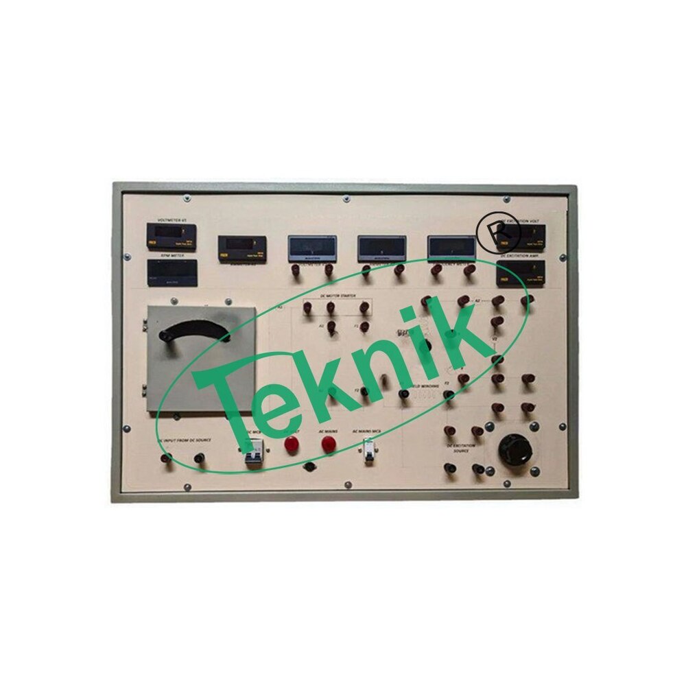
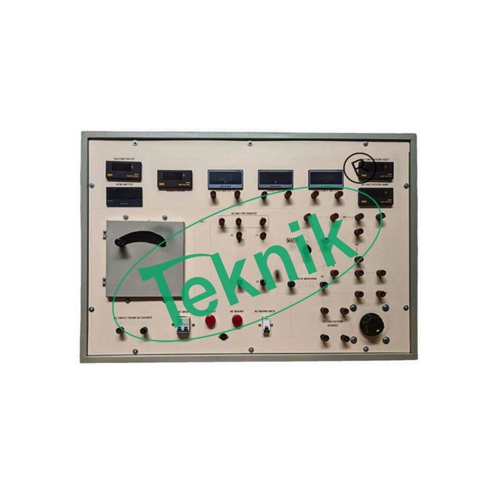

 Send Inquiry


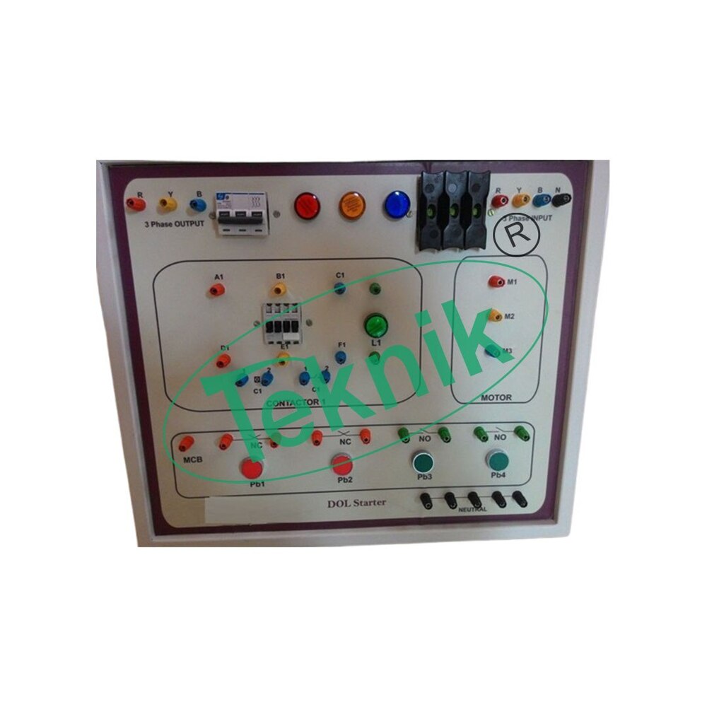
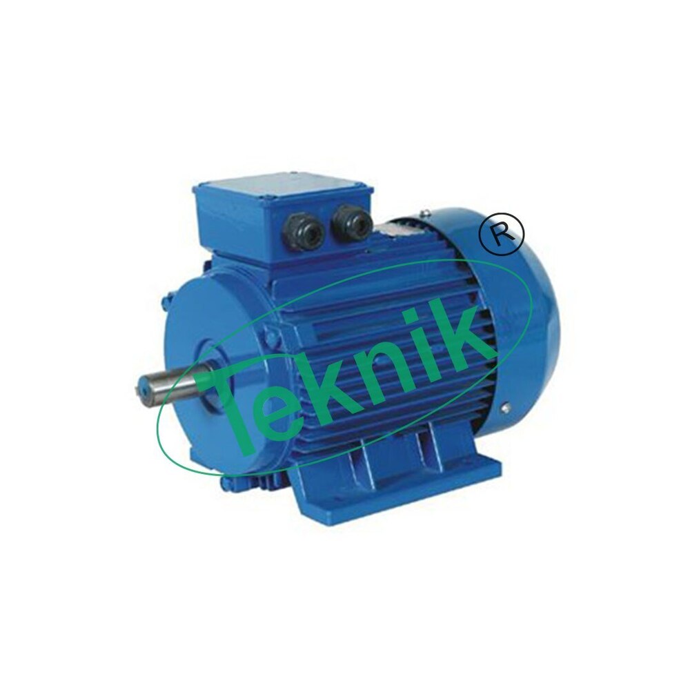
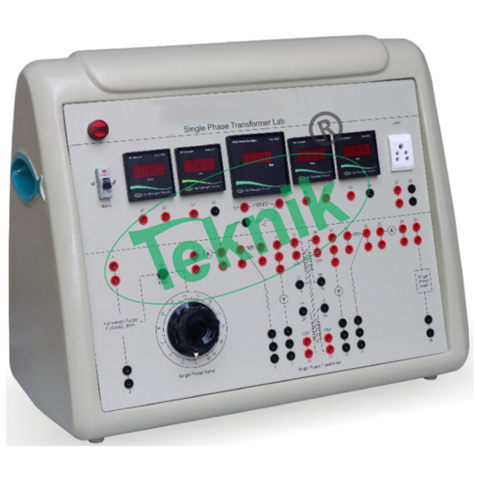
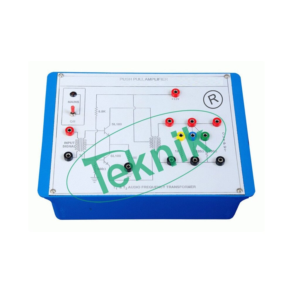


 Send Inquiry


 Send Inquiry
 Send SMS
 Call Me Free